Lighting device and illumination apparatus using same

a technology of lighting devices and illumination apparatuses, applied in the direction of electric variable regulation, process and machine control, instruments, etc., can solve the problems of increasing and achieve the effect of suppressing the increase in manufacturing cost and power loss

Active Publication Date: 2013-01-31
PANASONIC CORP
View PDF2 Cites 1 Cited by
  • Summary
  • Abstract
  • Description
  • Claims
  • Application Information

AI Technical Summary

Benefits of technology

[0010]In view of the above, the present invention provides an LED lighting device and an illumination apparatus using same to cover a wide range of load voltages while suppressing an increase in manufacturing cost and power loss.
[0015]The LED lighting device and the illumination apparatus in accordance with the aspect of the present invention has an effect of covering a wide range of load voltages while suppressing increases in manufacturing cost and power loss.

Problems solved by technology

However, when the winding number of the auxiliary coil is increased and, as a result, the ratio of a primary coil and the auxiliary coil approximates 1:1, a problem arises in which the effect of the coupling coefficient of the primary coil and the auxiliary coil remarkably appears and an oscillatory waveform of a frequency higher than an operating frequency is superimposed on the waveform of the electric current that flows to a switching element connected with the primary coil.
This leads to an increase in the manufacturing cost.
Moreover, there is also another problem in that the power loss increases due to the current-limiting resistor.

Method used


Image

  • Lighting device and illumination apparatus using same
  • Lighting device and illumination apparatus using same
  • Lighting device and illumination apparatus using same

Examples


Embodiment Construction

[0019]Hereinafter, embodiments of the present invention will be described with reference to the drawings which form a part hereof.

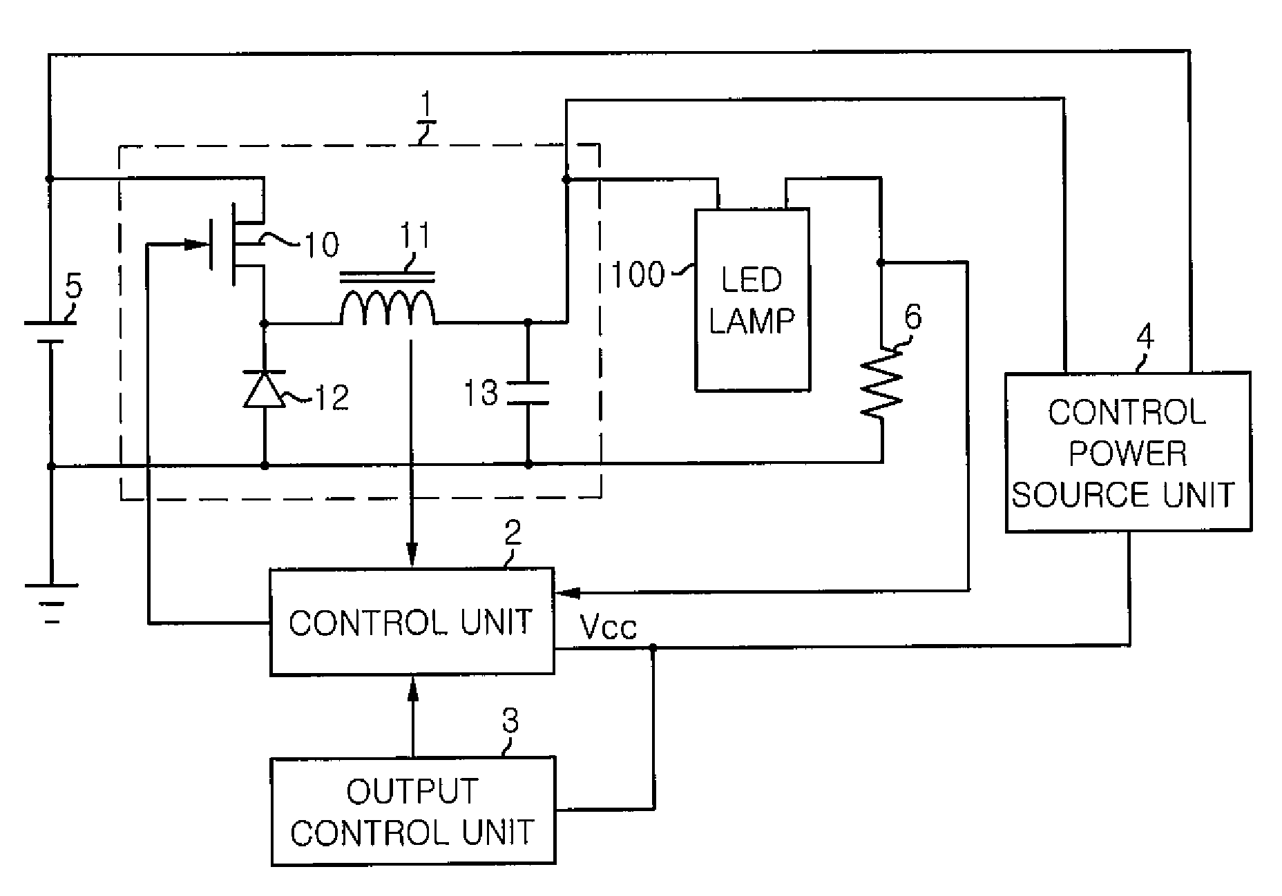
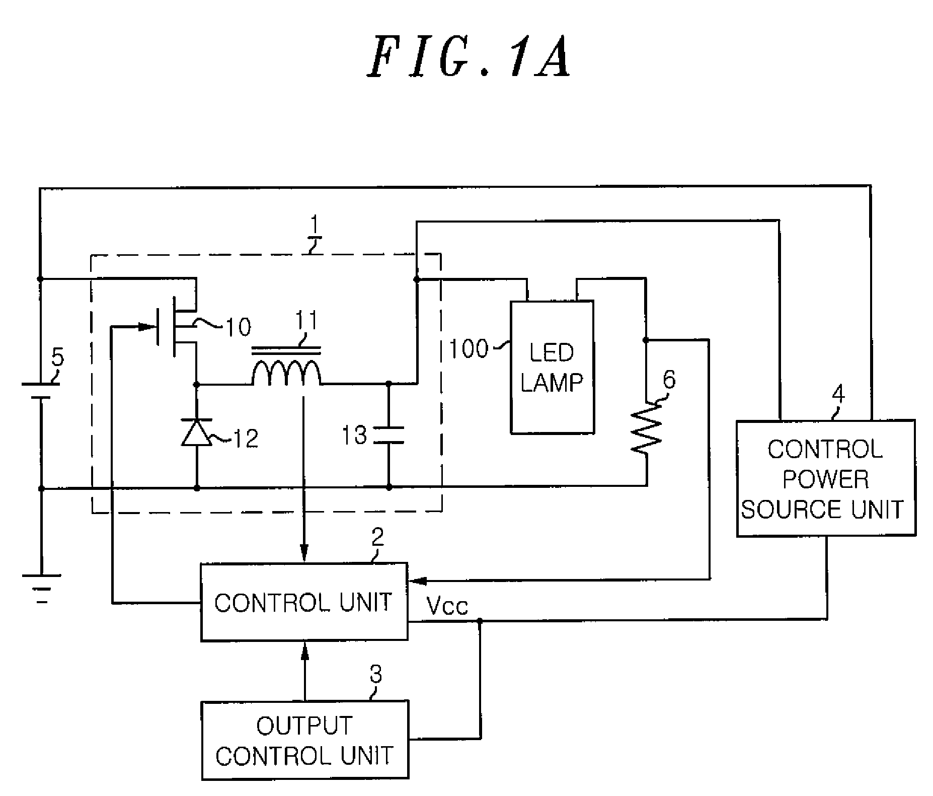
[0020]FIG. 1A is a schematic circuit diagram illustrating an LED lighting device in accordance with the embodiment of the present invention. The LED lighting device of the present embodiment includes a power source unit 1, a control unit 2 that controls the power source unit 1, an output control unit 3 that outputs a dimming instruction based on a dimming signal, which is transmitted from outside, to the control unit 2, and a control power source unit 4. In addition, in the present embodiment, an LED lamp which is described in the conventional art is presented as an example of a light-emitting diode which is lit by an LED lighting device, but the light-emitting diode is not limited thereto.

[0021]The power source unit 1 is configured by a well-known step-down chopper circuit and includes a series circuit of a switching element 10 and an inductor 11 inserte...


PUM


Abstract

An LED lighting device includes: a power source unit for supplying the DC output voltage to a light-emitting diode; a control unit for adjusting the DC output voltage; and a control power source unit for supplying a control power to the control unit. The control power source unit generates the control power with the DC output voltage and has: a current-limiting resistor for limiting an electric current that flows from the power source unit to the control unit; a constant voltage unit for converting a voltage to be applied to the control unit through the current-limiting resistor unit to a constant voltage; and a switching unit for switching a resistance value of the current-limiting resistor unit among a plurality of resistance values.

Description

FIELD OF THE INVENTION[0001]The present invention relates to an LED lighting device that lights a light-emitting diode (LED) and an illumination apparatus using same.BACKGROUND OF THE INVENTION[0002]Recently, LEDs have come into use as light sources for lighting in lieu of fluorescent lamps. For example, an LED lamp which is shaped like a conventional fluorescent lamp of a straight tube type is disclosed in Japanese Patent Application Publication No. 2009-43447. The LED lamp includes: a light source block having a structure in which a plurality of LEDs are mounted on a mounting substrate of a band plate shape; a glass tube of a straight tube type which stores the light source block therein; pin bases that block up both ends of the glass tube; and terminal pins that project from a side surface of the caps to feed a power to the light source block. Such an LED lamp is freely detachably mounted in a lamp socket provided in a dedicate illumination apparatus and is lit by the power (DC p...

Claims


Application Information

Patent Timeline
Patent Type & Authority Applications(United States)
IPC IPC(8): H05B37/02H05B44/00
CPCH05B33/0815H05B33/0842H05B45/37H05B45/395Y02B20/30
Inventor YAMAMOTO, MASAFUMIHAMAMOTO, KATUNOBUASANO, HIROYUKITAKIKITA, HISAYANAKAGAWA, HIROYUKIYOSHIMOTO, YUJI
Owner PANASONIC CORP
Why Eureka
Try Eureka