Unfortunately, typical shadow rendering techniques do not satisfactorily support rendering of finely detailed elements, such as fur or hair.
Also, because surfaces are generally classified as either “lit” or “unlit,” shadows from semitransparent surfaces and volumes, such as
fog, cannot be accurately represented.
While shadow maps may be satisfactory for rendering shadows of large, opaque objects, shadow maps do not work well for finely detailed geometry, such as hair, or semitransparent surfaces or volumes, such as
fog or
smoke.
This means that, in the case of very fine geometry,
stratified sampling does no better than unstratified sampling.
Since such conditions are rarely satisfied in practice, shadow maps for high-quality hair rendering are typically large and slow.
However, standard shadow maps do not behave well under compression.
Compression in x and y would entail fewer samples and thus greater error.
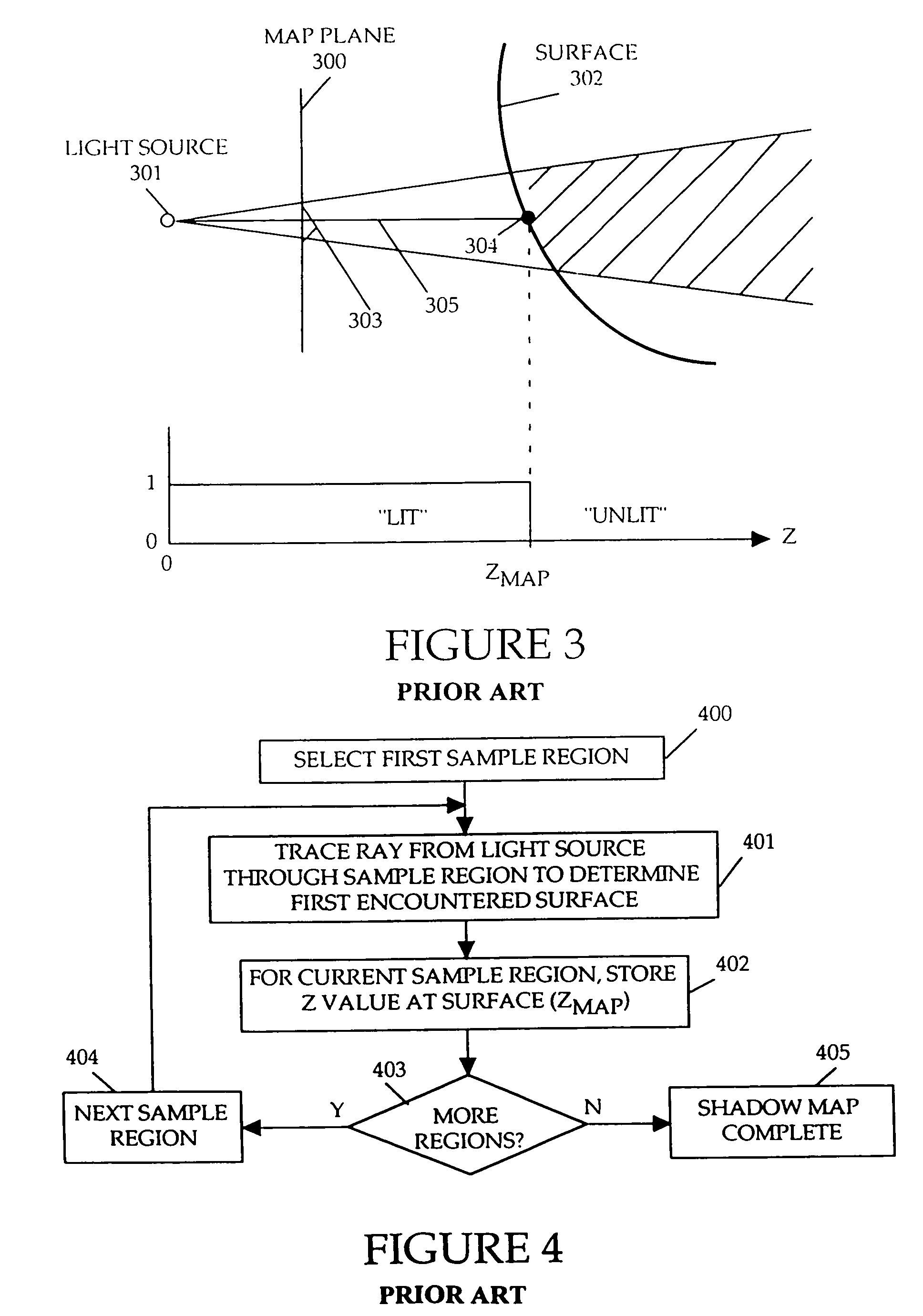
Compression in z, such as by reducing the number of bits representing z values in the shadow map, introduces a roundoff error in specifying the location of a first blocking surface.
Where the roundoff error causes ZMAP to be less than the actual value, the top surface will appear to be behind ZMAP, resulting in erroneous “self-shadowing” of the top surface.
In either of these scenarios, visible rendering errors will result.
However,
lossless compression is acceptable, but the compression ratios are relatively small and provide no significant space benefit.
Thus, compression is not a viable solution for standard shadow maps.
Ray casting can generate accurate shadows, but on scenes with very complex geometry,
ray casting is too expensive in terms of time and memory.
It is also difficult, other than by using an expensive area
light source, to soften shadows for artistic purposes, which in the case of standard shadow maps is achieved by simply increasing the filter width.
The main drawback is that 3D textures have a relatively coarse resolution, as well as a limited range and low accuracy in z (which creates bias problems).
A 3D texture with sufficient detail to capture accurate surface shadows would be prohibitively large.
Multi-layer depth images have been applied to the problem of shadow penumbras, but this technique otherwise has the same limitations as ordinary shadow maps.
However the surface shading process is much more complex when rendering objects made of translucent or thin materials, such as glass, marble, liquids, plastics, thin materials and the like.
Previous methods for shading translucent materials have relied complex calculations taking account of how light is absorbed and scattered through objects.
Drawbacks to this approach include that
ray-tracing and
diffusion calculations are highly complex and take long times to compute.
Other drawbacks include that if the user is not satisfied about how the final object appears in an image (e.g. the material is too dense), the user redefines the material properties (e.g. absorption and scattering properties), but then the user must again wait until the entire
simulation is complete to see the results.
Accordingly, any user adjustments to the scene cannot be imaged quickly.
Drawbacks to this approach include that the subset of locations typically vary from image to image.
The problem may not be obvious when viewing a
single image, however, when viewing a series of images, the surface of the object will undulate and sparkle.

