Method and system for representing wells in modeling a physical fluid reservoir

Inactive Publication Date: 2012-11-29
HAZLETT RANDY DOYLE +1
View PDF1 Cites 21 Cited by
  • Summary
  • Abstract
  • Description
  • Claims
  • Application Information

AI Technical Summary

Benefits of technology

[0018]The invention comprises the reduction of a generalized equation describing the productivity of an arbitrarily-oriented well segment within a subterranean fluid reservoir to a readily useable form of evaluation with unprecedented accuracy, consisting of a sum of direct, analytic formulas and fast-converging, exponentially-damped series summations, and subsequent use of this new method on a computer to accomplish new tasks, such as, but not limited to, productivity modeling of wells of arbitrary trajectory, including those with multiple intersecting wellbores. The invention also encompasses the interlacing of a new well equation in numerical reservoir simulators with wells below the resolution of the grid system used to define the reservoir size, shape, and heterogeneous property distribution and the use of such equations for feedback control on flux or well pressure within the simulator. The invention is capable of accurately modeling multiple wells simultaneously with sealed boundaries or with permeable boundaries through use of boundary integral equations. The invention is robust and adaptable to well constraints on either flux o

Problems solved by technology

However, the physical size of a wellbore, nominally 6 inches, is far below the resolution of most numerical reservoir simulations.
In order to capture smaller scale effects, some practitioners use local grid refinement around wells (U.S. Pat. No. 6,907,392, U.S. Pat. No. 7,047,165, U.S. Pat. No. 7,451,066, U.S. Pat. No. 6,078,869, U.S. Pat. No. 6,018,497), dramatically increasing the computational overhead with greater risk of problem numerical instability.
The application of horizontal drilling technology made the prior set of well equation rules obsolete, as hydrocarbon reservoirs are typically laterally extensive but thin.
While breakthroughs in modeling were found, this next generation of mathematical solutions was not without limitations regarding complexity of reservoir description and allowed well configurations.
Furthermore, the computational time is a substantial burden in numerical schemes for certain sets of input parameters.
The boundary condition most often imposed is that of a sealed system; however, many reservoirs have leaky sides through which the influx of water is possible, resulting in delayed pressure decline.
Still, prior art using semi-analytical solutions did not entirely replace the older Peaceman-type methods using empirical well connections.
In addition to complex geometry in hydraulically fractured shale, early transient behavior dominates economic forecasts, and pseudo-steady state may never be attained.
Such models require considerable computational resources and extensive inputs not generally amenable to field measurement or laboratory verification.
However, these solutions, when applied to box-shaped rectangular domains, become computationally challenging.
While this is indeed a statement of the problem solution, it has not been cast in a readily computable form.
In particular, the triple infinite series contains mathematical singularities, converges very slowly, and becomes increasingly difficult to evaluate as the observation point, (x, y, z) approaches the location of the point source, (xo, yo, zo).
Unfortunately, the observation point of most interest is one extremely nearby corresponding to the wellbore radius.

Method used


Image

  • Method and system for representing wells in modeling a physical fluid reservoir
  • Method and system for representing wells in modeling a physical fluid reservoir
  • Method and system for representing wells in modeling a physical fluid reservoir

Examples


Embodiment Construction

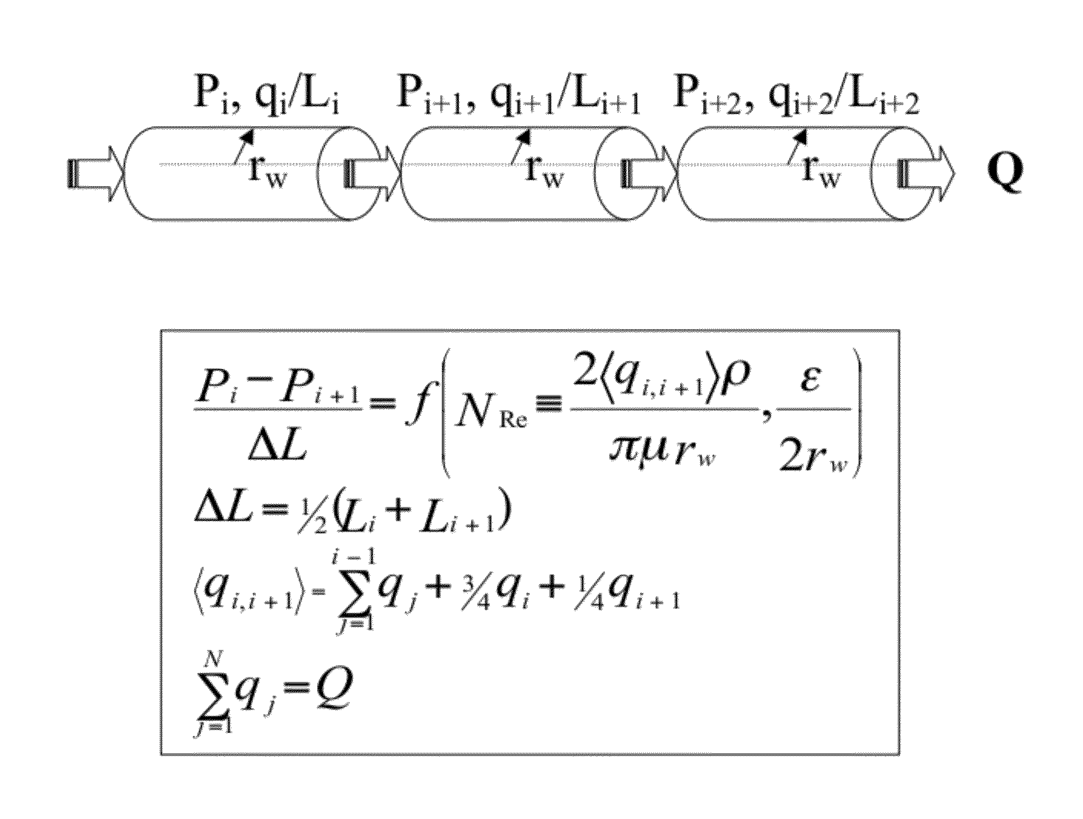
[0035]The invention pertains to solutions to the three-dimensional heat equation, given in a Cartesian coordinate system in terms of potential, Φ, as

kx∂2Φ∂x2+ky∂2Φ∂y2+kz∂2Φ∂z2=φμCt∂Φ∂t-f(x,y,z;xo,yo,zo).(1)

Here, (kx, ky, kz) denote the directional permeabilities of the medium through which fluid moves, Φ, μ, and Ct represent the porosity, fluid viscosity, and system compressibility, respectively, and the last term indicates a source or sink. Potential is interpreted as pressure, P, once gravitational forces are included. In terms of the Dirac delta function, δ, a RHS point source term is represented as

f(x,y,z;xo,yo,zo)˜δ(x−xo)·δ(y−yo)·δ(z−zo).  (2)

Using the two solutions given by Carslaw and Jaeger (1959) to the one-dimensional heat equation and the Neumann product rule, we have alternate expressions for the three-dimensional statement of the solution. One computes the departure from initial conditions as

PDC=abh8π3kxkykz·∫0t^Dtt3 / 2·[∑l=0∞-(2la±x±xo)24kxt]· [∑m=0∞-(2mb±y±yo)24kyt]·[∑...


PUM


Abstract

The disclosure is directed to a method of representing fluid flow response to imposed conditions in a physical fluid reservoir through wells. The invention utilizes techniques and formulas of unprecedented accuracy and speed for computer computation of Green's and Neumann functions in finite three-dimensional space for arbitrarily-oriented line sources in anisotropic media. The method includes the modeling of fluid flow in physical fluid reservoirs with an assemblage of linear well segments, characterizing arbitrary well trajectory, operating in unison with flux density coupled to flow rate within the well through a constitutive expression linking pressure distribution and flow. The method further includes generalization to complex fracture sets or fractured wells in modeling fluid flow in a reservoir, coupled use of such computations within a mesh representation of the physical fluid reservoir with isolation of well cell contributions, and extension to modeling of heterogeneous reservoirs and pressure transients.

Description

REFERENCE TO RELATED APPLICATIONS[0001]This application is a continuation-in-part (CIP) to previous application Ser. No. 12 / 436,779, filed May 7, 2009 by inventors Randy Doyle Hazlett and Desarazu Krishna Babu.ACKNOWLEDGMENT OF GOVERNMENT SUPPORT[0002]Not ApplicableCOMPACT DISC APPENDIX[0003]Not ApplicableBACKGROUND OF THE INVENTION[0004]1. Field of the Invention[0005]The invention pertains to the field of oil and gas well productivity modeling, and more particularly, to modeling the relationship between pressure gradient and fluid flux for the well and the surrounding hydrocarbon reservoir. More specifically, the invention relates to well productivity modeling for advanced well designs and to well connections for complex wells in numerical reservoir simulation methods.[0006]2. Description of Related Art[0007]The field of reservoir engineering includes modeling the capacity of wells to inject or withdraw fluids and the sustainability of production rates. The finite size and shape of...

Claims


Application Information

Patent Timeline
IPC IPC(8): G06F17/13
CPCE21B43/26E21B43/00
Inventor HAZLETT, RANDY DOYLEBABU, DESARAZU KRISHNA
Owner HAZLETT RANDY DOYLE
Why Eureka
Try Eureka