
Combined plate and cupholder

a combination plate and cupholder technology, applied in the field of housewares, can solve the problems of inability to fully meet the needs of use,

Inactive Publication Date: 2006-11-30
CRAWFORD KIM
View PDF5 Cites 32 Cited by
  • Summary
  • Abstract
  • Description
  • Claims
  • Application Information

AI Technical Summary

Benefits of technology

[0035] In accordance with a second aspect of the invention, a combined plate and cupholder is provided, including a plate having a planar base portion configured to support foodstuffs, and a rim coupled to the base portion and extending outward and upward therefrom to prevent foodstuffs from falling off the plate, the base portion having an aperture therethrough to receive and support a cup; and a cupholder disposed about the periphery of the aperture, the cupholder comprising a cupholder rim that is fixed to the base portion around the periphery of the aperture, and a locking collapsible cup support disposed in the aperture to support the bottom of the cup.
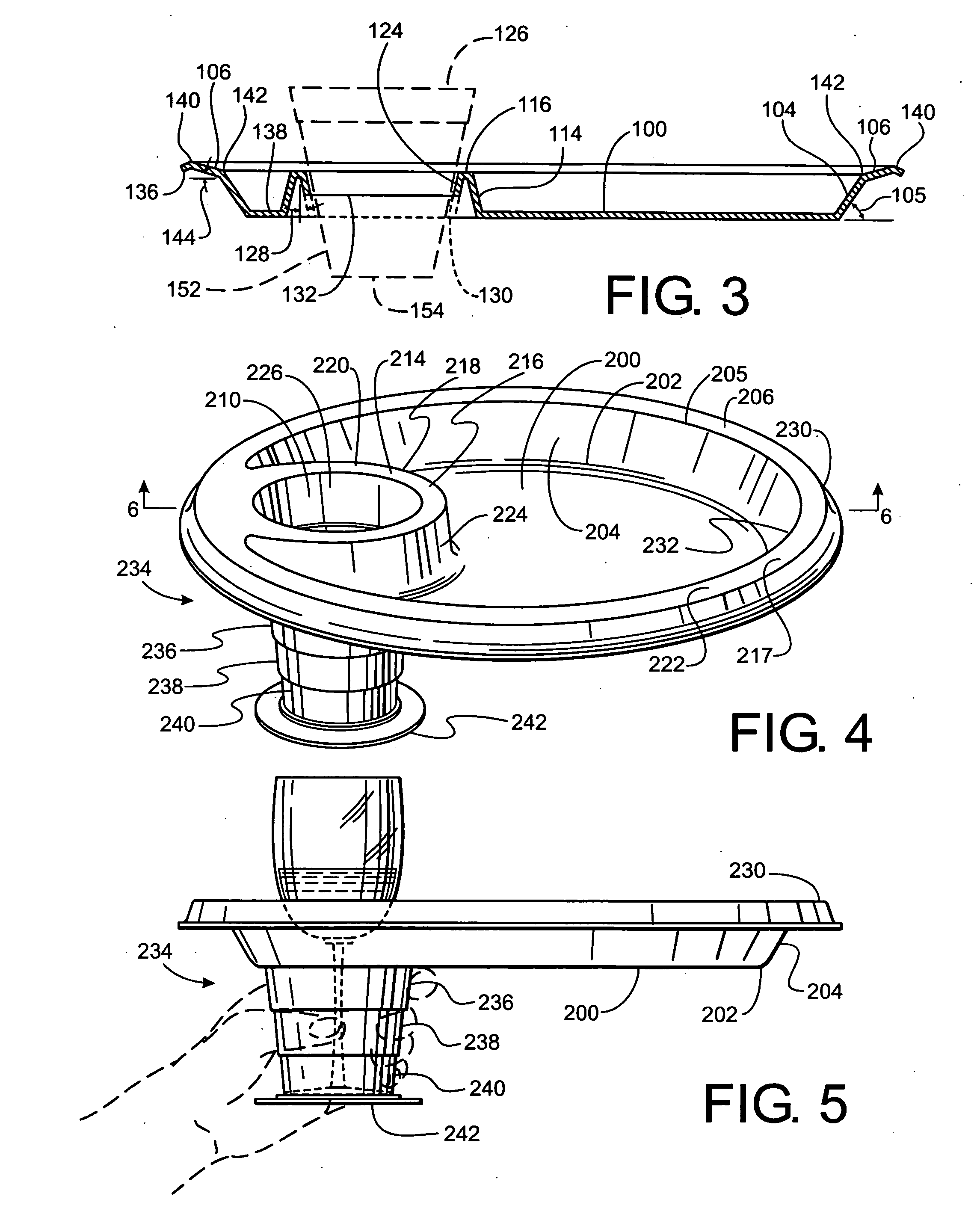
[0036] The locking collapsible cup support may also include a plurality of telescopically interengaged rings configured to lock together in frictional engagement to each other and to the cupholder rim. The plurality of rings may include at least a first ring configured to frictionally lock to the cupholder rim, and at least a second ring further comprising a base disposed to support the cup. The plurality of rings may include at least one ring disposed between and frictionally engageable to the first ring and the second ring to form a rigid telescopically extended body. The combined plate and cupholder may be made of transparent plastic and may be configured to support a transparent cup. The transparent cup may be a wine glass. One of the plurality of rings may include a means for preventing disassembly of the locking collapsible cup support. The means for preventing disassembly includes a flange that extends outwardly from one of said plurality of rings coupled to the first ring and is configured to interfere with the first ring and prevent the removal of said one of said plurality of rings from the first ring.

Problems solved by technology

By providing a portion of the tray for receiving a cup that is actually raised above the surface of the table when the tray is resting on the table, the combined tray and cupholder is inherently unstable and prone to tip.
This configuration doubles the height of the portable food tray with cupholder itself as compared to the height without the extended rim, and therefore makes the food tray take up much more space in storage.
All of these prior art devices suffer from several drawbacks.
By providing only a pad for the base of the cup leaves the cup perilously unsupported and prone to fall over and spill when the plate is carried about.
Unfortunately, this deep pocket arrangement is so elongated that the device cannot rest evenly on a flat surface.
Unfortunately, the portion of the cupholder extending up above the surface of the plate gets in the way of the plate and the user as the user eats.
This arrangement has its own problems, however, since the various pieces of the '672 patent are not fixed together, and can easily be separated from the plate portion and lost.
This will not prevent a top-heavy cup, e.g. those shown in FIGS. 2 and 6 herein from tilting to one side, twisting the telescopic rings with respect to each other, thereby tilting the base on which the cup rests, and spilling the cup.
Further, the arrangement is unstable.
A user who grasps the lower rings of the telescopic cup holder from the bottom may be surprised to find that the plate is completely unsupported.
This channel, however, divides the plate into multiple food compartments, thereby reducing its carrying capacity.

Method used


Image

  • Combined plate and cupholder
  • Combined plate and cupholder
  • Combined plate and cupholder

Examples


Embodiment Construction

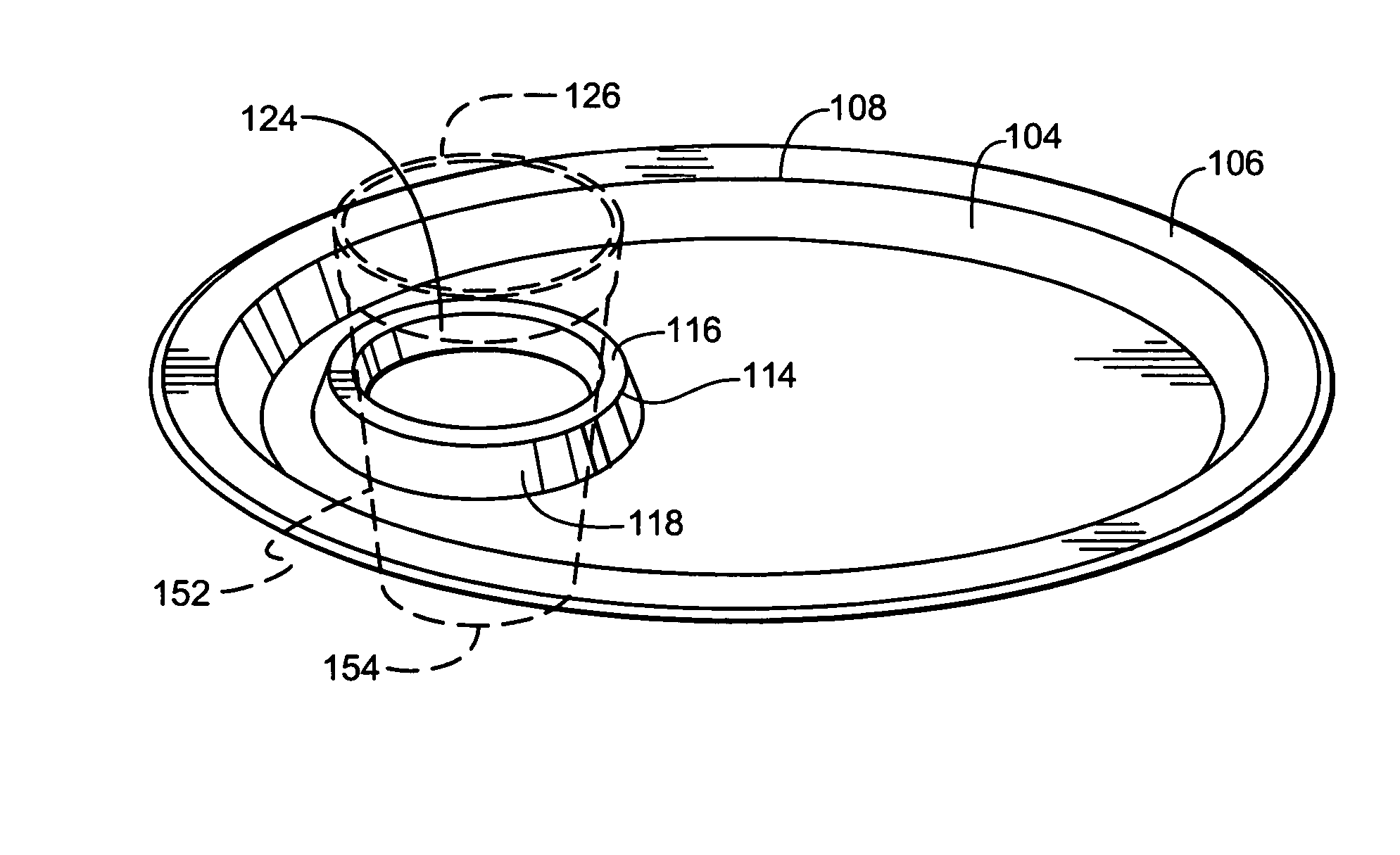
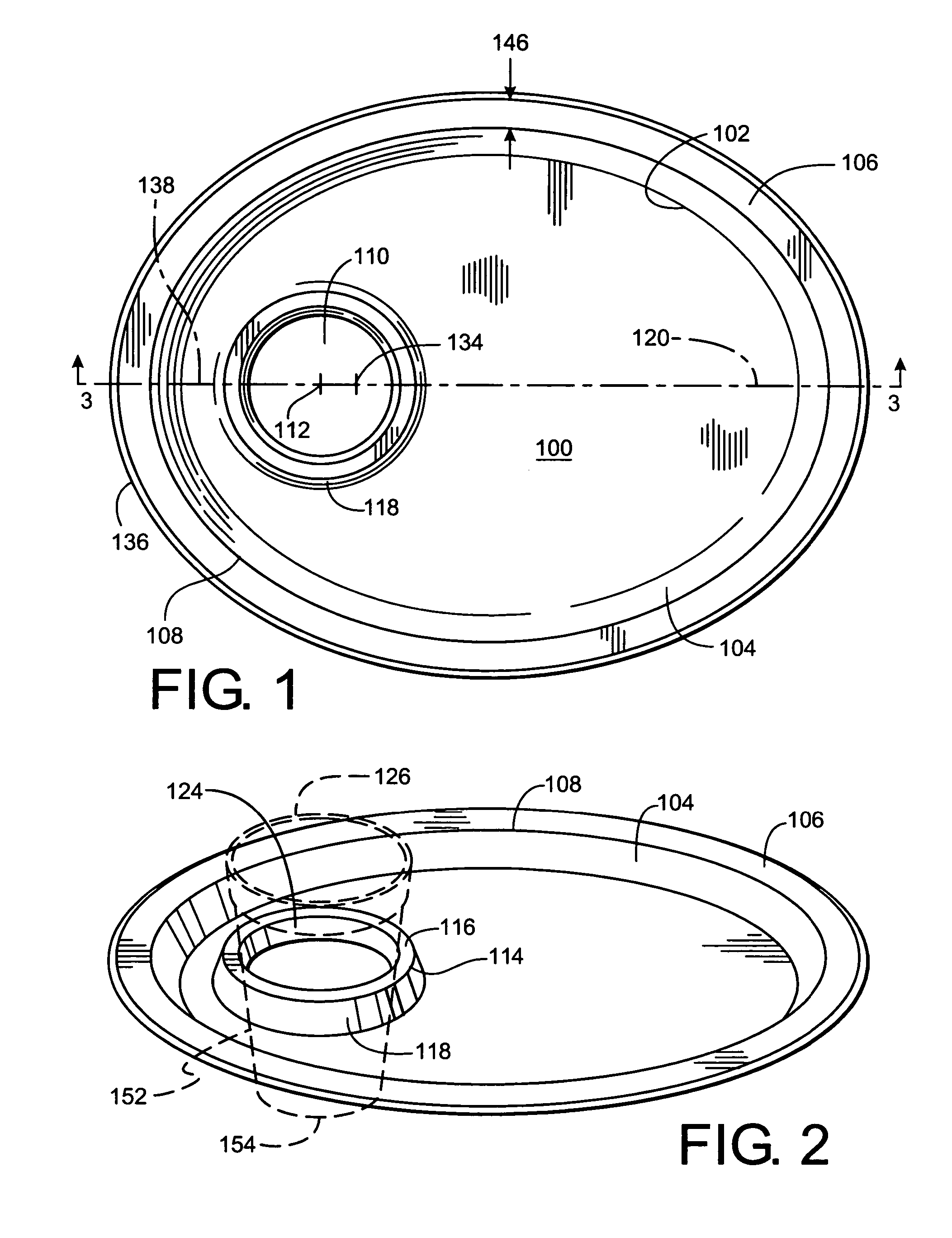
[0046] Referring now to FIGS. 1-3, a combined plate and cupholder is shown. The plate includes a planar base portion 100 that is elliptical and is configured to rest upon a flat surface such as a table. The planar base portion 100 constitutes substantially an entire ellipse, and has a peripheral elliptical edge 102 extending completely around the entire planar base portion 100. A generally outwardly tapered sidewall 104 is coupled to the base portion 100 along edge 102. Sidewall 104 defines an entire ellipse, and extends upward from the base portion 100 between 0.5 and 1.5 inches high. Sidewall 104 is preferably disposed at an angle 105 (FIG. 3) to base portion 100 of between 20° and 75° from the horizontal. An elliptical flange 106 is coupled to the top edge 108 of sidewall 104 and extends outward therefrom. Flange 106 is planar or a shallow conical section and is spaced a constant distance apart from base portion 100.

[0047] An aperture 110 having a center 112 is disposed at and e...


PUM


Abstract

A combined plate and cupholder includes a base portion with an aperture therethrough and a cupholder that extends around the periphery of the aperture that is raised above the base portion. A collapsible cup support may be inserted into the aperture that can be collapsed into a compact shape or extended below the bottom of the based portion and locked to form a rigid structure.

Description

FIELD OF THE INVENTION [0001] The invention relates generally to housewares. More particularly it relates to eating and drinking utensils. Even more particularly it relates to plates having structures configured to support or hold glasses, cups, or other drinking containers. BACKGROUND OF THE INVENTION [0002] Eating utensils such as saucers, platters, dishes, and the like (called “plates” hereinbelow), that are configured to hold solid food or semi liquid food and drinking utensils or beverage containers such as cups, glasses, stemware, wine glasses, snifters, mugs, sippy cups and the like (called “cups” hereinbelow) that are configured to be taken to the lips and from which fluids can be imbibed, are usually configured as separate devices. [0003] In certain situations, however, it is beneficial to specially configure plates and / or cups to mate with one another, thereby permitting a cup to support a plate, or a plate to support a cup. The primary benefit of this arrangement is that ...

Claims


Application Information

Patent Timeline
Patent Type & Authority Applications(United States)
IPC IPC(8): B65D21/02
CPCA47G19/065
Inventor CRAWFORD, KIM
Owner CRAWFORD KIM
Learn More