
Device, system, and method for providing a low-voltage fault ride-through for a wind generator farm

Inactive Publication Date: 2006-11-30
PERFECT GALAXY INT
View PDF23 Cites 110 Cited by
  • Summary
  • Abstract
  • Description
  • Claims
  • Application Information

AI Technical Summary

Benefits of technology

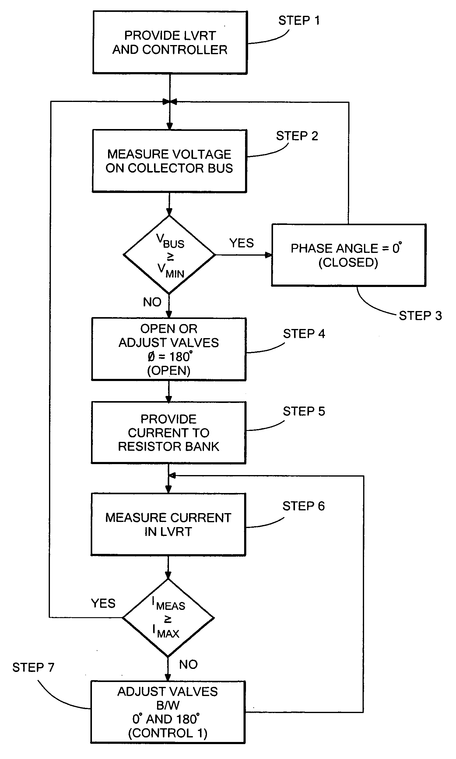
[0011] In accordance with the present invention, a system and a method are disclosed for use with a wind turbine generator (WTG) for controlling the voltage on a WTG collector bus that is electrically-coupled to a utility power grid. More specifically, the voltage is controlled to maintain a minimum voltage on the controller bus when a low-voltage, grid fault condition on the power grid is detected. The disclosed system and method prevent WTGs that are electrically-coupled to the collector bus from disconnecting from the power grid and thereby avoids the substantial restart time that is associated with such an event.
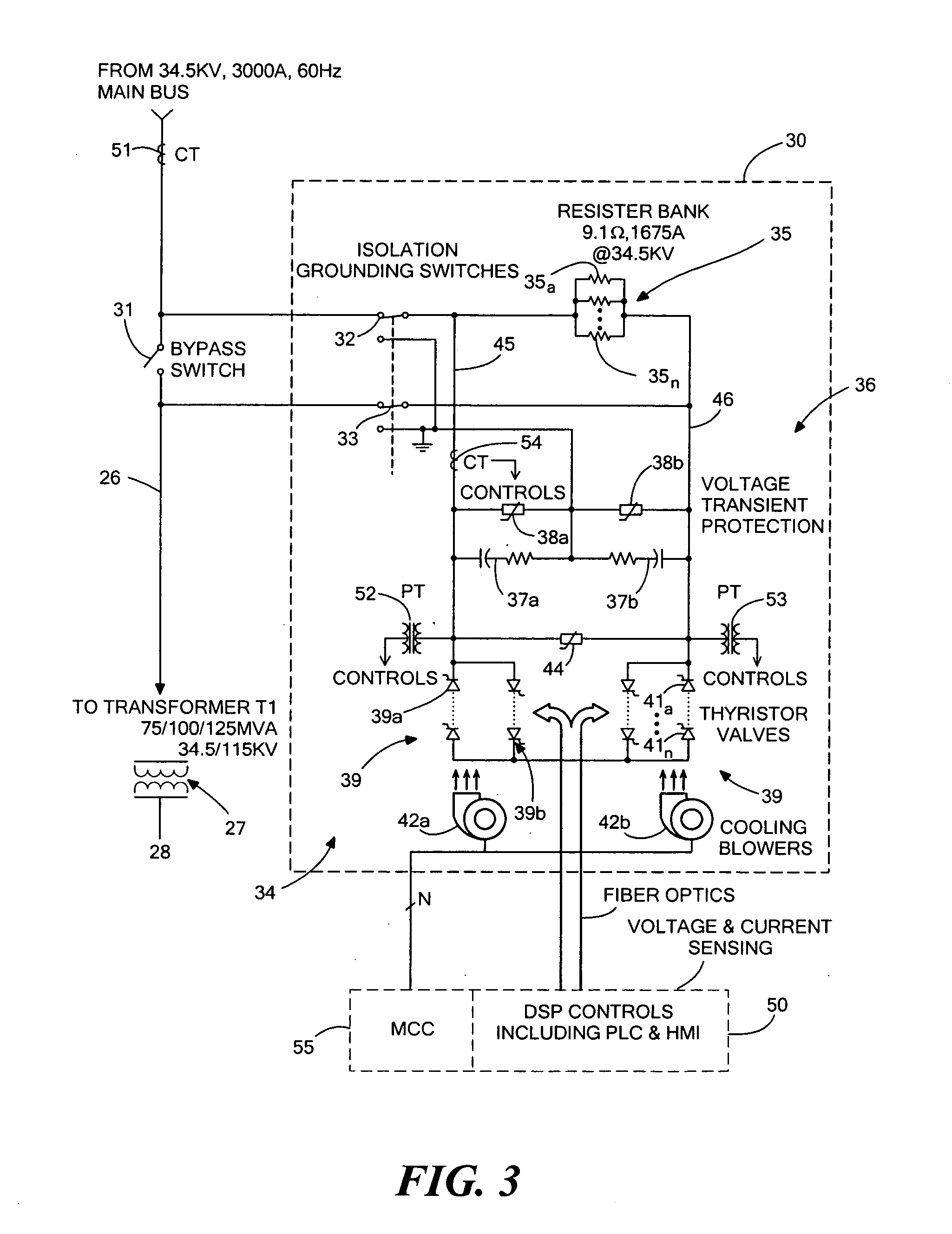
[0013] In one embodiment, a plurality of AC switching devices and a resistor bank are connected in parallel between the collector bus and the power grid. Each of the switches is rated to carry the full collector bus current for all or some portion of each phase and, further, to withstand some portion of the difference in voltage between the collector bus voltage and the voltage at the input to the step-up transformer coupled to the power grid. The resistor bank comprises at least one resistor. The resistor(s) is / are rated to carry the full phase voltage for a short period of time, e.g., the time needed to correct the low-voltage, grid fault occurrence on the utility grid. The resistor bank absorbs real power during the low-voltage, grid fault occurrence and produces a voltage that keeps the collector bus voltage above a threshold voltage level.
[0014] One embodiment of the presently disclosed system includes a plurality of AC switches, e.g., a silicon controlled rectifier or any other suitable controllable AC switching device that are arranged in multiple levels (to prevent damage from excessive voltage) and in such a way so that gating signals from the controller are applied to the switching devices simultaneously to specify the average current through the resistive element.
[0018] In another embodiment, a resistor bank is coupled between the collector bus and the power grid. The resistor bank comprises a plurality of resistors that are connected in parallel between the collector bus and the power grid. Switches are provided in series with each of the resistors so that each of the resistors can separately be included or excluded between the collector bus and the power grid under the control of the controller. Each of the resistors is rated to carry the full phase voltage for a short period of time, e.g., the time needed to correct the low-voltage, grid fault occurrence on the utility grid. In this embodiment, the resistors having corresponding switches closed define the equivalent resistance of the resistor bank at any given time. The resistor bank absorbs real power from the collector bus during the low-voltage, grid fault occurrence. The controller establishes the equivalent resistance of the resistor bank to maintain the voltage on the collector bus above a predetermined threshold voltage at which the WTGs disconnect from the power grid. In this embodiment, an AC switch is further provided in parallel with the resistor bank. When the AC switch is closed, current generated by the WTGs primarily passes through the AC switch to the power grid. The AC switch is closed during normal operation when the WTGs are providing current to the power grid. The AC switch may comprise silicon controlled rectifiers (“SCRs”), triacs or any other suitable controllable AC switching device.

Problems solved by technology

Although it is important to disconnect the WTG from the power grid to protect the WTG from a fault condition on the power grid, when a WTG disconnects from the power grid, it may take several minutes to go through a restart cycle and come back on line.
As a result, a transient voltage sag in the utility power grid, in the range of milliseconds, could cause a complete shutdown of an entire wind farm power source for several minutes.

Method used


Image

  • Device, system, and method for providing a low-voltage fault ride-through for a wind generator farm
  • Device, system, and method for providing a low-voltage fault ride-through for a wind generator farm
  • Device, system, and method for providing a low-voltage fault ride-through for a wind generator farm

Examples


Embodiment Construction

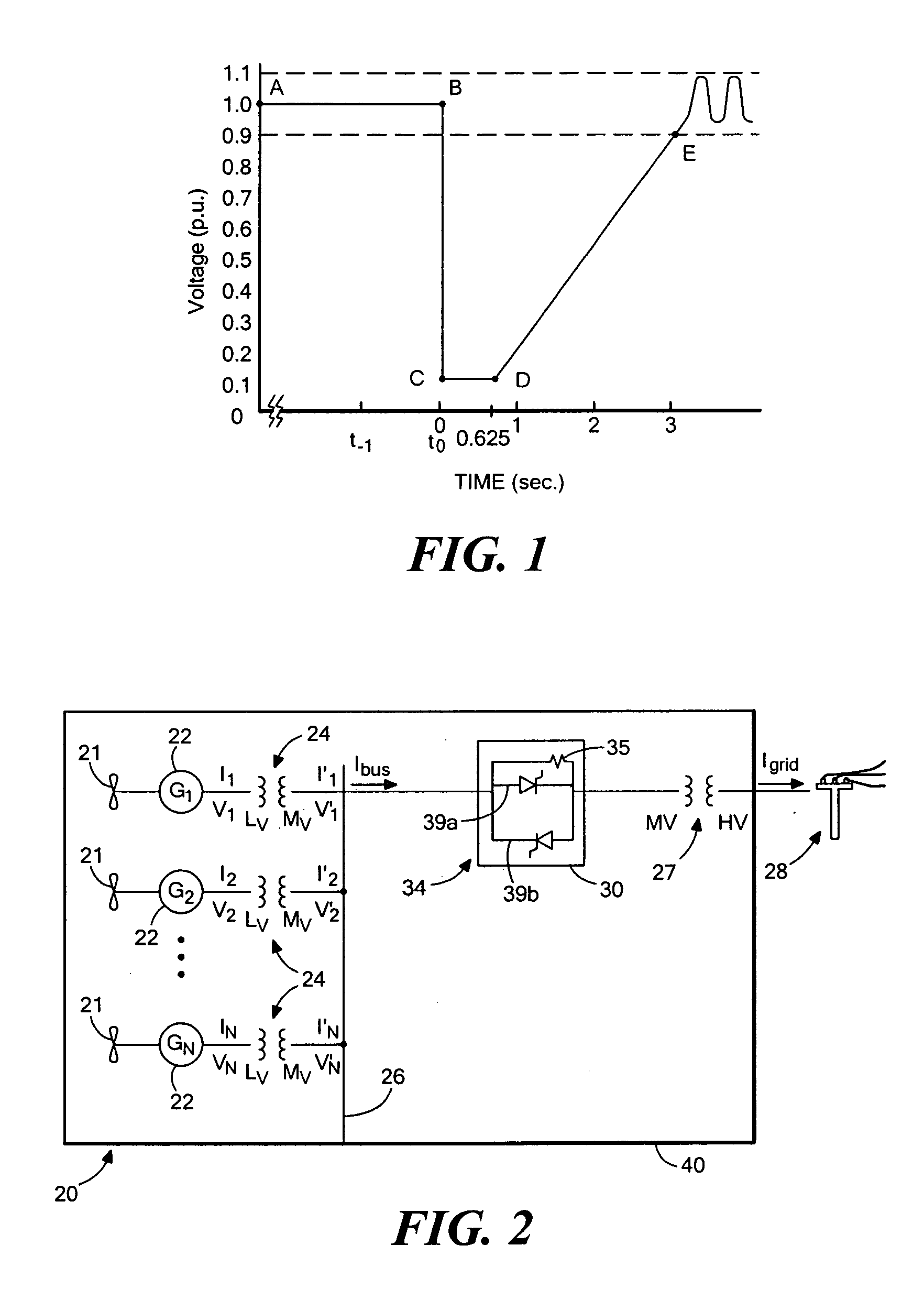
[0033] A low-voltage fault ride-through (“LVRT”) system is disclosed. The LVRT device is structured and arranged to prevent wind turbine generators in a wind farm or other doubly-fed induction machines (“DFIM”), from disconnecting from a utility power grid during transient low-voltage, grid fault occurrences on the power grid. For convenience, the system will be described for the case of a single-phase-to-ground system. The system, however, is equally applicable to two- and three-phase-to-ground systems as well as to one-, two-, and three-phase line-to-line systems. The presently disclosed system will also be described as applied to DFIM wind turbine generators, however, those of ordinary skill in the art will appreciate the general applicability of the system to all kinds of induction motors and wind turbine generators.

[0034] Referring to FIG. 2, there is shown a diagram of a system 40 in accordance with the present invention. The system 40 includes a current source 20, e.g., a pl...


PUM


Abstract

A device, a system, and a method for preventing power-producing wind turbine generators from tripping due to the detection of a low-voltage condition on a power grid are disclosed. The disclosed device includes a resistor bank that absorbs real power and a control system that maintains the collector bus voltage above a threshold voltage level during the duration of low-voltage condition on the power grid. Collector bus voltage is maintained using gating signals that include phase delay angles to adjust the opening / closing of the switching devices.

Description

CROSS REFERENCE TO RELATED APPLICATIONS [0001] This application claims the benefit of U.S. provisional patent application No. 60 / 684,416 filed on May 24, 2005, which is incorporated herein in its entirety by reference.BACKGROUND OF THE INVENTION [0002] The present invention generally relates to a device, a system, and a method for controlling the voltage on a wind farm collector bus during and after a low-voltage or grid fault occurrence on a utility power grid, to prevent the wind turbine generators from tripping and disconnecting from the power grid. [0003] There has been an increasing interest in non-fossil fuel energy sources as a consequence of the escalating cost and political ramifications associated with a reliance on foreign oil. Wind turbine generators (“WTGs”) are one such energy source. WTGs offer the further benefit of providing an environmentally-friendly, non-polluting energy source. [0004] WTGs are controlled current sources that normally deliver current at approxima...

Claims


Application Information

Patent Timeline
IPC IPC(8): G05F1/70
CPCF03D9/005G05F1/70H02P2101/15Y02E10/72H02P9/102F03D9/257
Inventor RAJDA, JANOSGALBRAITH, ANTHONY WILLIAMSCHAUDER, COLIN DAVID
Owner PERFECT GALAXY INT
Learn More