Method and apparatus for improving scheduling in packet data networks

a packet data network and packet data technology, applied in data switching networks, frequency-division multiplexes, instruments, etc., can solve the problems of service schedulers with significant challenges, many types of packet data traffic are delay sensitive, delay budgets, etc., to reduce or eliminate the violation of end-to-end delay budgets and increase the overall capacity of scheduling

Inactive Publication Date: 2006-11-30
UNWIRED PLANET
View PDF14 Cites 50 Cited by
  • Summary
  • Abstract
  • Description
  • Claims
  • Application Information

AI Technical Summary

Benefits of technology

[0007] A packet data scheduler and corresponding scheduling methods provide packet data delivery scheduling for incoming (delay sensitive) packet data based on considering the incoming delays of the packet data. Incorporating knowledge of the incoming delays, e.g., the packet ages and / or transit network delays, into the scheduler's operations reduces or eliminates the violation of end-to-end delay budgets, and increases the scheduler's overall capacity for handling such data.

Problems solved by technology

In particular, many types of packet data traffic are delay sensitive and have maximum delay budgets associated with them.
Constrained delay budgets present service schedulers with significant challenges.
However, if some of the packet data to be delivered by the scheduler over the air interface has a maximum delay budget associated with it, the scheduler may be forced to schedule such data for delivery, even if the user(s) targeted to receive the data are not in good radio conditions.
More particularly, the conventional scheduler does not know how much of the delay budget has already been consumed by the time it receives a given data packet for transmission, and thus it does not know how much delay budget time remains available for scheduling actual delivery of that packet to the targeted user(s) via transmission over the air interface.

Method used


Image

  • Method and apparatus for improving scheduling in packet data networks
  • Method and apparatus for improving scheduling in packet data networks
  • Method and apparatus for improving scheduling in packet data networks

Examples


Embodiment Construction

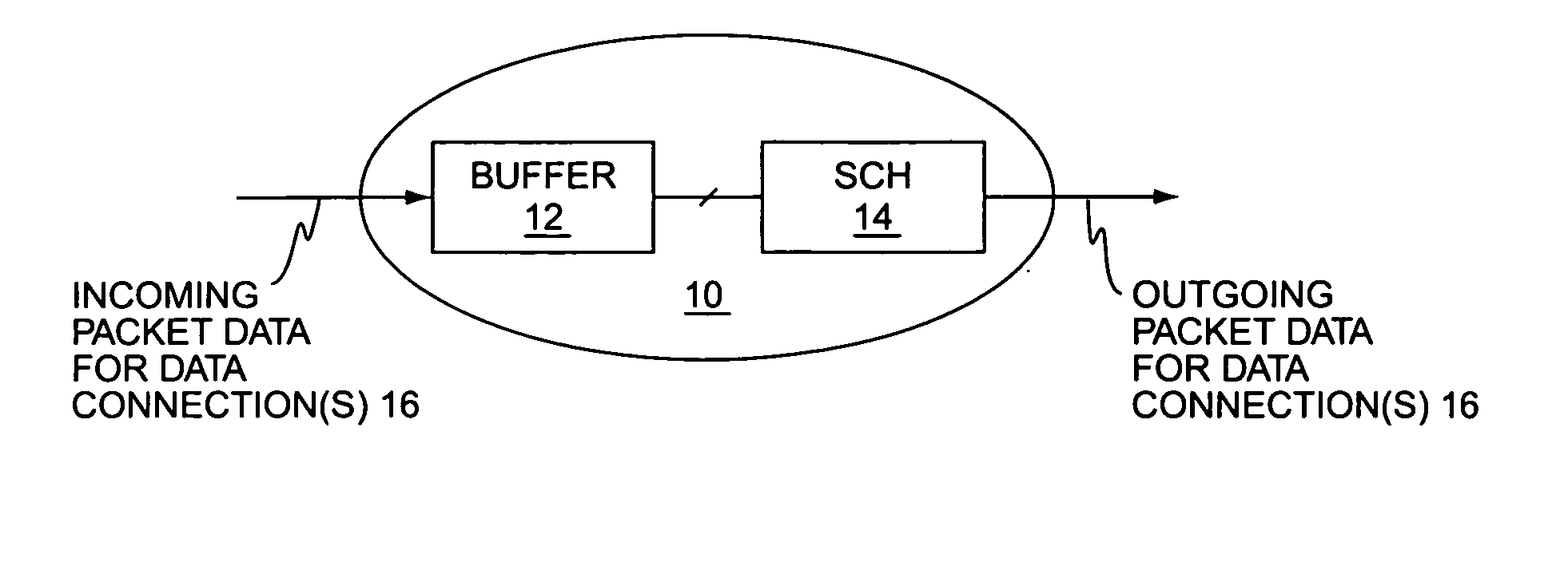
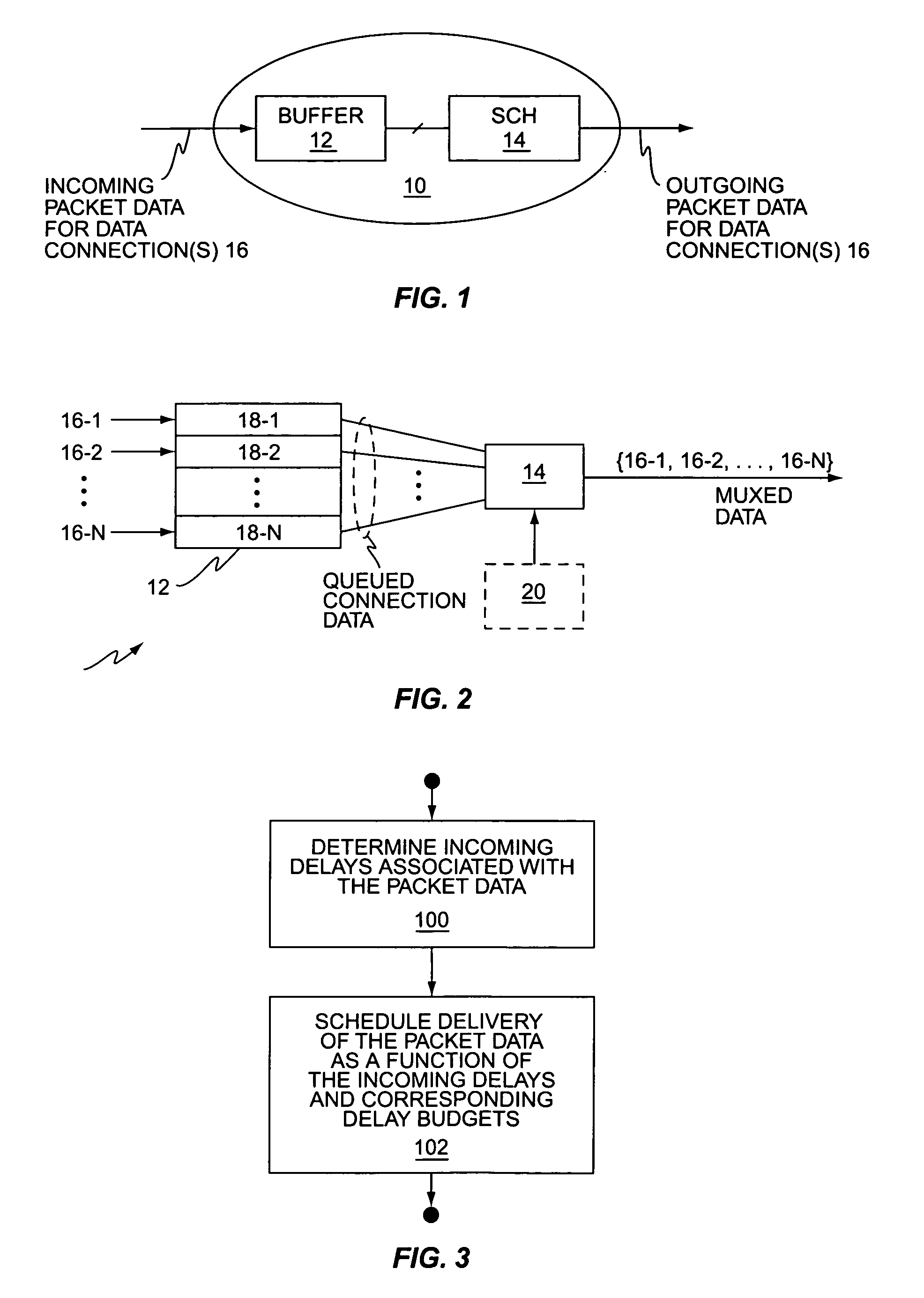
[0025]FIG. 1 illustrates a network node 10, including a buffer 12 and a packet data service scheduler 14. The node 10, which may be an intermediate node or a terminating node, receives incoming packet data for one or more logical data connections 16, and outputs that packet data according to a delivery schedule managed by the scheduler 14. As used herein, the term “logical data connection” generally connotes a given end-to-end data connection, such that the packet data traffic for that end-to-end connection flows through the node 10 as a distinct packet data stream.

[0026] Rather than simply pass through incoming packet data as it is received, the scheduler 14 of the node 10 schedules the “delivery” (i.e., output) of the packet data according to a defined scheduling algorithm. As explained later herein, such scheduling may be necessary where the delivery targets are wireless communication terminals having differing service requirements and dynamically changing radio conditions, but ...


PUM


Abstract

A method of scheduling packet data delivery by a communication network node uses knowledge of the incoming delays and corresponding delay budgets associated with the packet data to be scheduled. For example, a wireless communication network base station may serve a plurality of users via a time-multiplexed packet data channel, and may schedule the delivery of packet data targeted to individual ones of those users based on determining the allowable scheduling delays for the incoming packet data it receives for those users. The allowable scheduling delays for packet data received on a given data connection may be determined based on the incoming delays associated with that packet data and the corresponding end-to-end delay budget defined for that packet data. The incoming delays may be calculated from packet time information, e.g., timestamps, and/or may be estimated based on call type, network type, network distances/locations, network conditions, etc.

Description

BACKGROUND [0001] The present invention generally relates to packet data communication networks, such as wireless communication networks adapted for packet data services, and particularly relates to improving service scheduling in such networks. [0002] Service scheduling plays an increasingly prevalent role in at least some types of packet data networks. For example, wireless communication networks, such as cellular radio networks, commonly use service schedulers on the forward and / or reverse radio links to control the scheduling of data transmissions to selected users or groups of users. In such scenarios, it is common for a radio base station to maintain data queues for incoming packet data targeted for delivery to individual mobile stations, or groups of mobile stations, whose packet data connections with the radio network are being supported by the radio base station. [0003] A service scheduler within the radio base station transmits data from individual queues according to over...

Claims


Application Information

Patent Timeline
Patent Type & Authority Applications(United States)
IPC IPC(8): H04J1/16H04L12/56H04L12/54
CPCH04L47/10H04L12/5693H04L47/50
Inventor LUNDSTROM, STIG ANDERS
Owner UNWIRED PLANET
Why Eureka
Try Eureka