Designated router assginment per multicast group address/range

a router and multicast technology, applied in the direction of digital transmission, data switching network, electrical equipment, etc., can solve the problem of overburdening the processing bandwidth of the router r

Active Publication Date: 2006-11-30
CISCO TECH INC
View PDF14 Cites 87 Cited by
  • Summary
  • Abstract
  • Description
  • Claims
  • Application Information

AI Technical Summary

Problems solved by technology

This could lead to overburdening the processing bandwidth of router RF, at least when compared to the processing bandwidth of routers RG and RH.

Method used


Image

  • Designated router assginment per multicast group address/range
  • Designated router assginment per multicast group address/range
  • Designated router assginment per multicast group address/range

Examples


Embodiment Construction

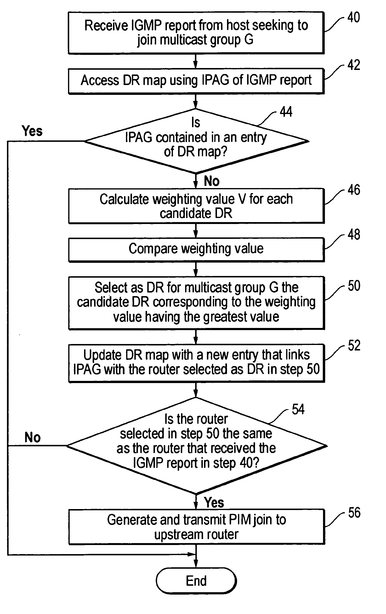
[0021] Disclosed is an apparatus or method for assigning separate DRs to multicast groups or range of multicast groups. Using the present invention, for example, the DR assigned to a first multicast group or range of multicast groups is distinct from the DR assigned to a second multicast group or range of multicast groups. The present invention enables data packets for the first multicast group or range of multicast groups to be transmitted to a LAN via a DR that is distinct from the DR that transmits data packets to the LAN for the second multicast group or range of multicast groups. The present invention will be described with reference to a network employing IPv4, it being understood that the present invention may be implemented in a network employing IPvV6.

[0022] The present invention can be employed in a router or other device (e.g., a general purpose or special purpose completer) which is configured to function as a router. Embodiments within the scope of the present inventio...


PUM


Abstract

Each of several routers connected to a LAN elects the same router as the designated router for a multicast group identified by a multicast address. Each of the several routers implements a method for electing the designated router. The method includes in one embodiment, generating several values corresponding to the several routers, respectively. The several values are generated as a function of the several routers' IP addresses, respectively, and an IP address of a first multicast group. The values, in one embodiment, are then compared to determine which is the largest. Thereafter each router elects as the designated router for the multicast group, the router corresponding to the largest value.

Description

BACKGROUND OF THE INVENTION [0001] Unicast and multicast are two well-known techniques for transmitting data packets between sources and receivers via a packet-switched network (hereinafter network). Unicast is a point-to-point communication technique in which data packets are transmitted between a single source and a single receiver. Multicast allows a source or several sources to transmit data packets simultaneously to select receivers, i.e., those receivers in a multicast group. During multicast transmission, data packets are replicated by multicast enabled routers at points within the network where the communication path diverges to separate receivers of a multicast group. In this fashion, multicast protocols deliver data to multiple receivers without burdening the source or consuming excessive network bandwidth. [0002] There are several different multicast protocols including: protocol independent multicast-dense mode (PIM-DM), protocol independent multicast-sparse mode (PIM-SM...

Claims


Application Information

Patent Timeline
Patent Type & Authority Applications(United States)
IPC IPC(8): H04L12/56
CPCH04L45/00
Inventor BOERS, ARJENWIJNANDS, IJSBRAND
Owner CISCO TECH INC
Why Eureka
Try Eureka