Image printing apparatus

a technology of image printing and rollers, applied in the direction of electrographic process equipment, printing, instruments, etc., can solve the problems of delay in conveyance, stained roller pairs, and disturbed toner image on the transfer sh

Inactive Publication Date: 2006-11-30
KONICA MINOLTA BUSINESS TECH INC
View PDF4 Cites 30 Cited by
  • Summary
  • Abstract
  • Description
  • Claims
  • Application Information

AI Technical Summary

Benefits of technology

[0011] The present invention has been made in consideration of the above situation, and can provide an image printing apparatus which can correct variations in inter-sheet distance at the time of conveyance of transfer sheets.

Problems solved by technology

If, therefore, a transfer sheet is sandwiched and conveyed by the roller pair, the toner image on the transfer sheet is disturbed, and the roller pair is stained.
In addition, when a transfer sheet enters between the heat roller and pressure roller of the fixing section, the sheet may strike one of the roller surfaces and slip to cause a delay in conveyance.
It therefore cannot help but ensure a sufficient inter-sheet distance between transfer sheets.
Ensuring a sufficient inter-sheet distance will decrease the image printing efficiency.
Even this technique cannot prevent the above trouble in conveyance.
In addition, since slip may occur between, for example, convey rollers and a transfer sheet when the convey direction is reversed, if a sufficient inter-sheet distance cannot be ensured between transfer sheets to be continuously conveyed, the transfer sheets may collide with each other.
This leads to a decrease in image printing efficiency.
An increase in image printing speed is limited by deterioration in image quality, sticking of a transfer sheet to the photosensitive drum, and a restriction on the rotational speed of a polygon motor used for laser beam scanning.
However, the image printing apparatus disclosed in patent reference 1 is designed to correct the problem of an inter-sheet distance shortage which occurs at the time of feed operation, but is not designed to correct variations in inter-sheet distance due to problems in the above image printing process and problems in conveyance at the time of sheet reversing operation.
If, for example, the convey velocity is changed during the printing process to ensure a sufficient inter-sheet distance, a deterioration in image quality occurs.
In some cases, mechanical operation in the post-processing apparatus cannot cope with large variations in the timing of the delivery of transfer sheets.

Method used


Image

  • Image printing apparatus
  • Image printing apparatus
  • Image printing apparatus

Examples


Embodiment Construction

Arrangement of Image Printing Apparatus

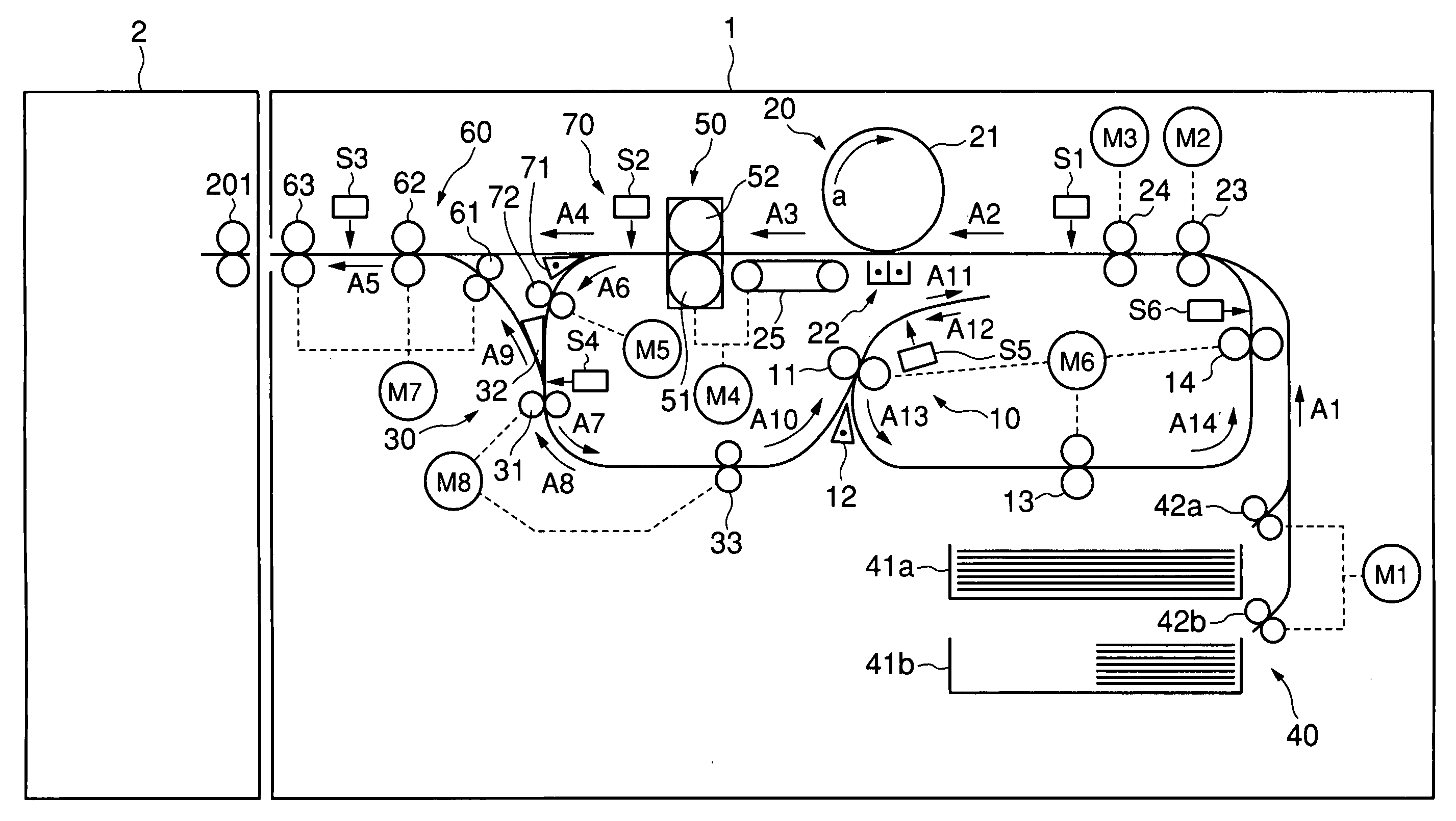
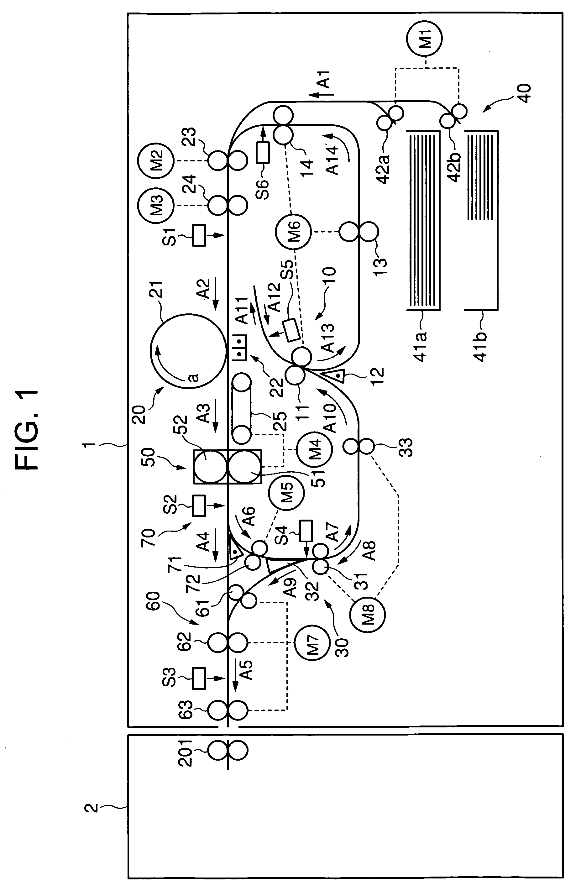
[0077] The arrangement of an image printing apparatus 1 according to an embodiment of the present invention will be described first with reference to FIG. 1. FIG. 1 is a sectional view showing the schematic overall arrangement of the image printing apparatus 1.

[0078] The image printing apparatus 1 performs printing operation in accordance with a delivery mode or a print mode. The delivery mode and the print mode will be described below. The print mode includes a “single-side image printing mode” of printing on only one surface (obverse surface) of a transfer sheet and delivering the sheet and a “duplex image printing mode” of printing on both surfaces (obverse and reverse surfaces) of a transfer sheet and delivering the sheet. The “single-side image printing mode” includes a “straight delivery mode” of delivering a transfer sheet with its printed surface facing upward and an “reverse delivery mode” of delivering a transfer sheet with its pri...


PUM


Abstract

An image printing apparatus, which can correct variation in inter-sheet distance at the time of conveyance of transfer sheets, comprising an image printing section which performs image printing by sequentially conveying a plurality of transfer sheets at predetermined intervals at a first convey velocity and performing transfer and fixing of a toner image on each transfer sheet, a timepiece section which measures a time required for the image printing section to perform image printing on the each transfer sheet, and a delivery convey section which receives each transfer sheet on which image printing is performed by the image printing section and delivers the each transfer sheets while adjusting intervals therebetween by conveying the each transfer sheets upon changing the convey velocity to a second convey velocity set on the basis of the measured time required for the image printing on the each transfer sheet.

Description

CROSS-REFERENCE TO RELATED APPLICATION [0001] This application makes reference to, incorporation the same herein, and claims all benefits accruing under 35 U.S.C. §119 from an application for Image Printing Apparatus earlier filed in the Japanese Patent Office on May 27, 2005, and there duly assigned No. 2005-155008. BACKGROUND OF THE INVENTION [0002] 1. Field Of The Invention [0003] The present invention relates to an image printing apparatus and, more particularly, to a technique of printing an image in an image printing apparatus by transferring a toner image formed on a photosensitive drum onto a transfer sheet and thermally fixing the image. [0004] 2. Description Of Related Art [0005] Electrophotographic image printing apparatuses have been conventionally used for copying machines, printers, and the like. In an electrophotographic image printing apparatus, first of all, while a uniformly charged photosensitive drum as an image carrying body is moved (rotated), its surface is ex...

Claims


Application Information

Patent Timeline
Patent Type & Authority Applications(United States)
IPC IPC(8): G03G15/00
CPCG03G2215/00599G03G15/6564G03G15/235G03G2215/00945
Inventor OKAMOTO, AKIRAYAMAUCHI, KAZUMICHIYOSHIMURA, KAZUTOSHI
Owner KONICA MINOLTA BUSINESS TECH INC
Why Eureka
Try Eureka