Catalyst deterioration detection device

a detection device and catalyst technology, applied in mechanical equipment, machines/engines, electric control, etc., can solve the problems of catalyst not being able to reduce lean components in exhaust gas, catalyst discharged from catalyst contains a large amount of nox, and the oxygen release period and oxygen storage period are not varied, so as to eliminate the variation in the oxygen release period and oxygen storage period, the effect of accurately determining the oxygen storage amoun

Inactive Publication Date: 2009-11-26
TOYOTA JIDOSHA KK
View PDF7 Cites 25 Cited by
  • Summary
  • Abstract
  • Description
  • Claims
  • Application Information

AI Technical Summary

Benefits of technology

[0021]The first aspect of the present invention detects the catalyst's maximum oxygen storage state and minimum oxygen storage state while exercising control to provide the rich or lean target air-fuel ratio for the internal combustion engine. Further, the first aspect of the present invention determines the oxygen storage amount, which is the amount of oxygen released or stored during the oxygen release period or oxygen storage period between the maximum oxygen storage state and minimum oxygen storage state, and judges the deterioration of the catalyst in accordance with the oxygen storage amount. The maximum or minimum oxygen storage state is detected in accordance with the output of the oxygen sensor installed downstream of the catalyst. Therefore, if the output of the oxygen sensor varies depending on a difference in the output detection conditions for the oxygen sensor, the detection of the maximum or minimum oxygen storage state varies, thereby varying the oxygen release period or oxygen storage period.
[0022]In this respect, the first aspect of the present invention sets up the oxygen storage amount detection conditions for correcting a variation that may occur in the oxygen release period or oxygen storage period depending on the difference in output detection conditions for the oxygen sensor. This makes it possible to eliminate the variation in the oxygen release period and oxygen storage period and accurately determine the oxygen storage amount. Therefore, the deterioration of the catalyst can be detected with increased accuracy.
[0023]Meanwhile, if, for instance, the exhaust gas flow rate or flow velocity is high in a situation where the intake air amount is large, the change per unit time in the concentration of each component in the exhaust gas becomes great. Therefore, when the intake air amount is large, the oxygen sensor responds to changes in the exhaust gas air-fuel ratio at increased sensitivity and changes its output with increased responsiveness. Therefore, when the exhaust gas air-fuel ratio prevailing downstream of the catalyst changes to a lean or rich air-fuel ratio, the response speed at which the oxygen sensor generates an output to indicate such a change is higher when the intake air amount is large than when the intake air amount is small. Therefore, when the intake air amount is large, the maximum or minimum oxygen storage state is detected earlier than when the intake air amount is small. As a result, the oxygen release period and oxygen storage period, which are periods between the maximum oxygen storage state and minimum oxygen storage state, are short when the intake air amount is large and long when the intake air amount is small.
[0024]In this respect, when control is exercised during the oxygen release period or oxygen storage period to provide a rich or lean target air-fuel ratio as the air-fuel ratio of the internal combustion engine, the second aspect of the present invention ensures that the amount of air-fuel ratio change from the current air-fuel ratio to the rich or lean target air-fuel ratio is based on the intake air amount. Further, when control is exercised to switch from a current target air-fuel ratio to the rich or lean target air-fuel ratio, the second aspect of the present invention gradually changes the target air-fuel ratio in accordance with the air-fuel ratio change amount before the target air-fuel ratio reaches the rich or lean target air-fuel ratio. Therefore, the period required for the air-fuel ratio to reach the target air-fuel ratio can be adjusted in accordance with the intake air amount. This makes it possible to reduce the variation in the oxygen release period or oxygen storage period, which is based on a variation in the intake air amount. As a result, the oxygen storage amount can be accurately detected.
[0025]Further, even when the exhaust gas concentration changes in the same manner, the diffusion speeds of exhaust gas components may differ from each other due to a variation in the element temperature of the oxygen sensor. As a result, the actual exhaust gas and the exhaust gas reaching an exhaust side electrode of the oxygen sensor may differ in the concentrations of their components. Therefore, the speed at which the oxygen sensor indicates a lean or rich output in response to the same exhaust gas concentration change varies with the element temperature of the oxygen sensor. Therefore, the timing with which the maximum or minimum oxygen storage state is detected varies with the element temperature of the oxygen sensor.
[0026]In this respect, when control is exercised during the oxygen release period or oxygen storage period to provide a rich or lean target air-fuel ratio as the air-fuel ratio, the third aspect of the present invention sets the rich or lean target air-fuel ratio in accordance with the element temperature. This ensures that when the exhaust gas air-fuel ratio prevailing downstream of the catalyst switches to a rich or lean air-fuel ratio, the rich or lean air-fuel ratio, that is, the concentration of a rich or lean component of the exhaust gas, is set in accordance with the element temperature. Therefore, in an environment where, for example, the exhaust gas concentration is greatly influenced by the diffusion speed difference based on the element temperature of the oxygen sensor, the concentration of each component of the exhaust gas can be increased to minimize the influence. This makes it possible to detect the maximum or minimum oxygen storage state with increased accuracy, thereby minimizing the variation in the length of the oxygen release period or oxygen storage period.

Problems solved by technology

However, if this state continues for an extended period of time, the catalyst stores oxygen to its full oxygen storage capacity and can no longer reduce NOx and the like.
Therefore, the exhaust gas discharged from the catalyst contains large amounts of HC and CO.
When, on the other hand, the catalyst reaches the maximum oxygen storage state, the catalyst cannot reduce lean components in the exhaust gas.
Therefore, the exhaust gas discharged from the catalyst contains a large amount of NOx.

Method used


Image

  • Catalyst deterioration detection device
  • Catalyst deterioration detection device
  • Catalyst deterioration detection device

Examples


first embodiment

[System Configuration of First Embodiment]

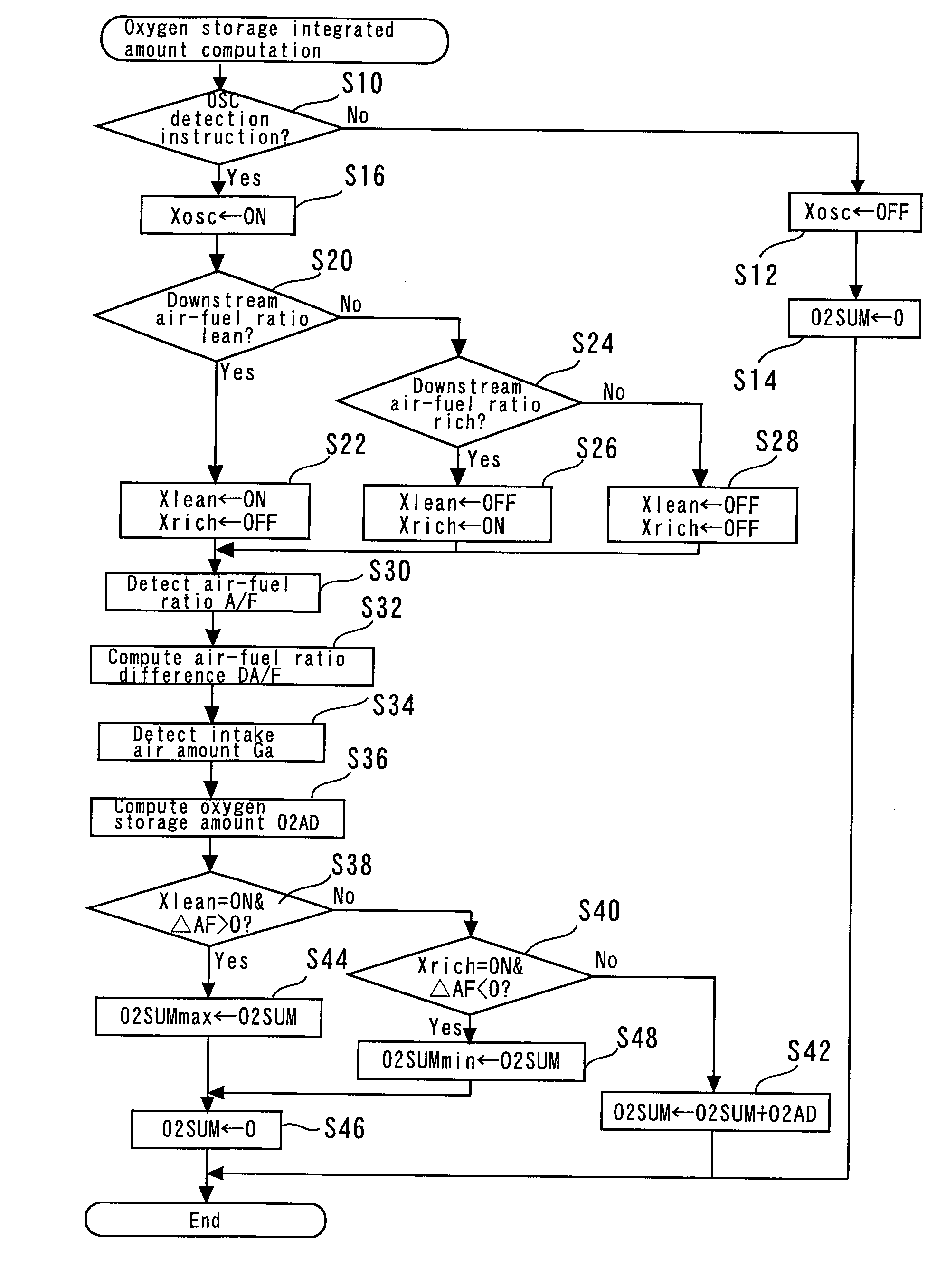
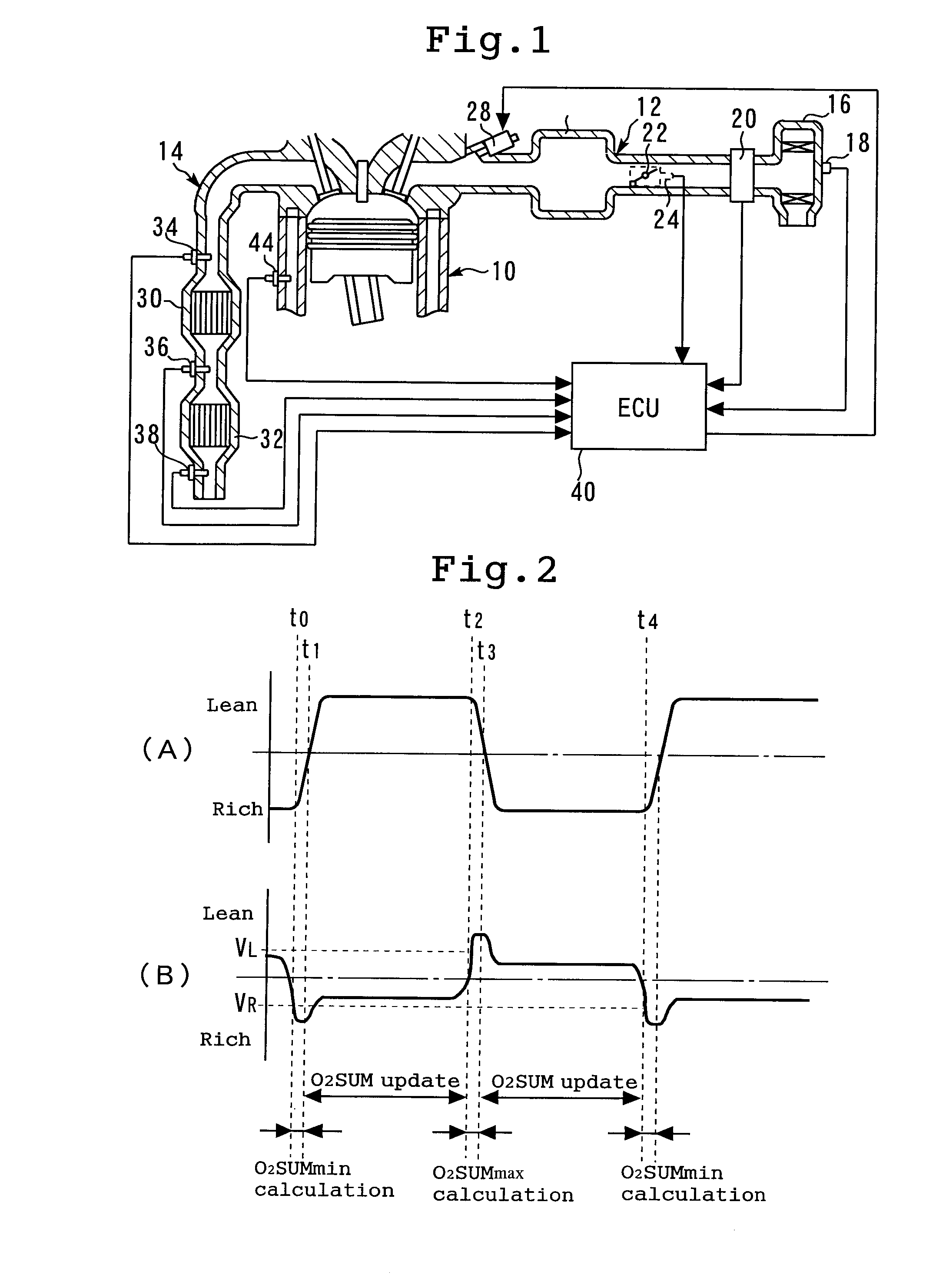
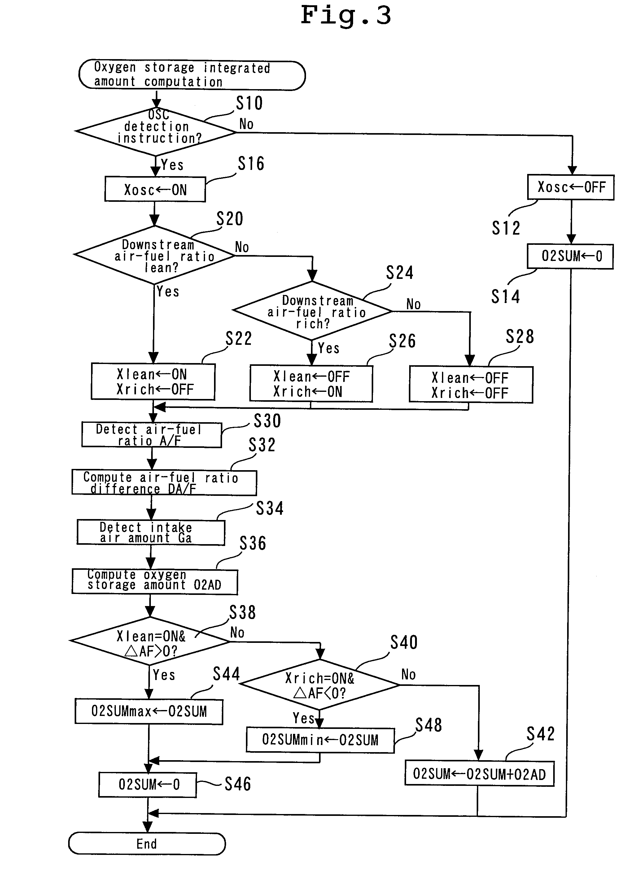
[0065]FIG. 1 is a schematic diagram illustrating the structure of an internal combustion engine 10 having a catalyst deterioration detection device according to a first embodiment of the present invention and the structures of its peripheral parts. Referring to FIG. 1, the internal combustion engine 10 communicates with an intake path 12 and an exhaust path 14. The intake path 12 has an air filter 16, which is positioned at an upstream end. The air filter 16 incorporates an intake temperature sensor 18, which detects intake air temperature (that is, ambient temperature). An air flow meter 20 is positioned downstream of the air filter 16. The air flow meter 20 is a sensor that detects the amount of intake air Ga that flows in the intake path. A throttle valve 22 is installed downstream of the air flow meter 20. A throttle sensor 24 is positioned near the throttle valve 22 to detect the opening of the throttle valve 22. A fuel injection valve ...

second embodiment

[0137]The catalyst deterioration detection device according to a second embodiment of the present invention and a system around it have the same configuration as described in conjunction with the first embodiment (see FIG. 1). In the second embodiment, too, the ECU 40, which serves as the catalyst deterioration detection device, detects the deterioration of the upstream catalyst 30 by detecting the oxygen storage capacity of the upstream catalyst 30. More specifically, the second embodiment exercises air-fuel ratio forced control in the same manner as the first embodiment, detects the oxygen storage capacity of the catalyst during the execution of such control, and judges the deterioration of the catalyst in accordance with the oxygen storage capacity.

[0138]More specifically, the catalyst deterioration detection device according to the second embodiment exercises the same control as the catalyst deterioration detection device according to the first embodiment except that the former ...

third embodiment

[0163]The catalyst deterioration detection device according to a third embodiment of the present invention and a system including the catalyst deterioration detection device have the same configuration as described in conjunction with the first embodiment (see FIG. 1). The catalyst deterioration detection device according to the third embodiment exercises air-fuel ratio forced control to switch to a rich or lean air-fuel ratio as is the case with the catalyst deterioration detection device according to the first or second embodiment, determines the oxygen storage capacity OSC by detecting the oxygen storage integrated amount O2SUMmax, O2SUMmin in the maximum or minimum oxygen storage state, and judges the deterioration of the upstream catalyst 30 in accordance with the oxygen storage capacity OSC. The catalyst deterioration detection device according to the third embodiment exercises the same control as the device according to the second embodiment except that the former uses a pred...


PUM


Abstract

The present invention detects the deterioration of a catalyst. In accordance with an output from an oxygen sensor, a catalyst deterioration detection device for the catalyst positioned in an exhaust path of an internal combustion engine detects a maximum oxygen storage state where an exhaust gas outflowing downstream of the catalyst contains excess oxygen and a minimum oxygen storage state where the exhaust gas outflowing downstream of the catalyst lacks oxygen. Control is exercised to provide a rich target air-fuel ratio for the internal combustion engine during an oxygen release period between the instant at which the maximum oxygen storage state is detected and the instant at which the minimum oxygen storage state is detected later, and to provide a lean target air-fuel ratio for the internal combustion engine during an oxygen storage period between the instant at which the minimum oxygen storage state is detected and the instant at which the maximum oxygen storage state is detected later. Further, the amount of oxygen released from the catalyst during the oxygen release period or the amount of oxygen stored by the catalyst during the oxygen storage period is detected as an oxygen storage amount. The deterioration of the catalyst is then judged in accordance with the oxygen storage amount. Moreover, when exercising control for catalyst deterioration detection, the catalyst deterioration detection device sets up oxygen storage amount detection conditions for correcting a variation that may occur in the oxygen release period or the oxygen storage period depending on a difference in output detection conditions for the oxygen sensor.

Description

TECHNICAL FIELD[0001]The present invention relates to a catalyst deterioration detection device, and more particularly to a catalyst deterioration detection device for detecting the deterioration of a catalyst that purifies exhaust gas of an internal combustion engine.BACKGROUND ART[0002]A catalyst for exhaust gas purification is positioned in an exhaust path of a vehicle-mounted internal combustion engine. The catalyst is capable of storing an appropriate amount of oxygen. If the exhaust gas to be purified by the catalyst contains HC, CO, and other unburned components, the oxygen stored by the catalyst oxidizes such unburned components. If, on the other hand, the exhaust gas contains NOx and other oxides, the catalyst reduces such oxides. The resulting oxygen is then stored in the catalyst.[0003]The catalyst positioned in the exhaust path purifies the exhaust gas by oxidizing or reducing the components of the exhaust gas as described above. Thus, the purification capability of the ...

Claims


Application Information

Patent Timeline
Patent Type & Authority Applications(United States)
IPC IPC(8): F01N11/00F02D41/18F01N3/20
CPCF01N11/007F01N2550/02F02D41/0295F01N13/0093F02D2200/0816Y02T10/47F02D2200/0814Y02T10/40
Inventor AOKI, KEIICHIRO
Owner TOYOTA JIDOSHA KK
Why Eureka
Try Eureka