Polyaxial bone screw with compound articulation

Active Publication Date: 2006-11-30
NUVASIVE
View PDF99 Cites 134 Cited by
  • Summary
  • Abstract
  • Description
  • Claims
  • Application Information

AI Technical Summary

Benefits of technology

[0011] Therefore, objects of the present invention include providing a polyaxial bone screw assembly with features that may be readily, securely fastened to each other and to bone. A further object of the invention is to provide a polyaxial bone screw assembly with increased angular articulation. Furthermore, it is an object of the invention to provide a lightweight, low profile polyaxial bone screw assembly that may be assembled prior to implantation and also assembles in such a manner that the components cooperate to create an overall structure that prevents unintentional disassembly. Another

Problems solved by technology

This is sometimes very difficult or impossible to do.
Consequently, heavy, bulky implants are undesirable and lighter implants with a relatively small profile both in height and width are more desirable.
However, a drawback to smaller, lighter implants is that they may be more difficult to rigidly fix to each other and into a desired angular position.
La

Method used


Image

  • Polyaxial bone screw with compound articulation
  • Polyaxial bone screw with compound articulation
  • Polyaxial bone screw with compound articulation

Examples


Embodiment Construction

[0025] As required, detailed embodiments of the present invention are disclosed herein; however, it is to be understood that the disclosed embodiments are merely exemplary of the invention, which may be embodied in various forms. Therefore, specific structural and functional details disclosed herein are not to be interpreted as limiting, but merely as a basis for the claims and as a representative basis for teaching one skilled in the art to variously employ the present invention in virtually any appropriately detailed structure.

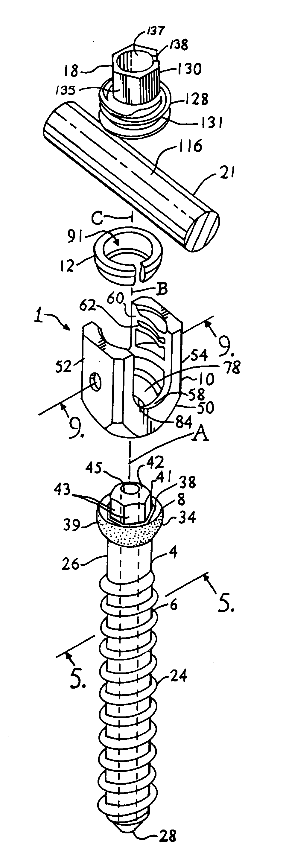
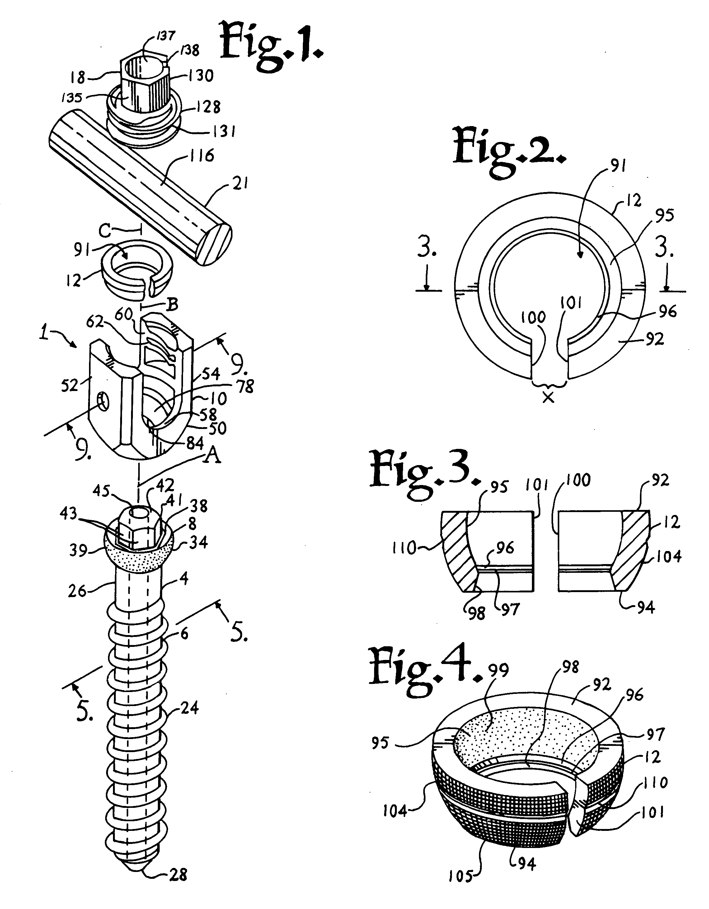
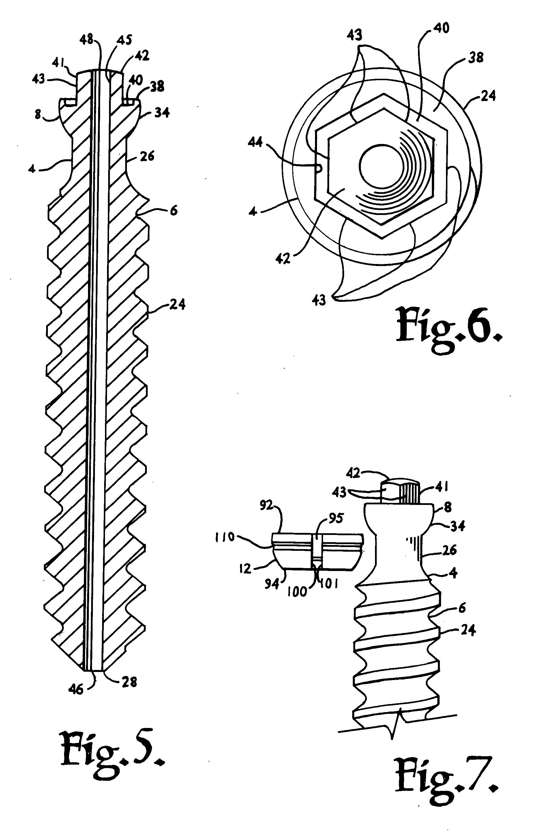
[0026] With reference to FIGS. 1-12, the reference numeral 1 generally represents a polyaxial bone screw assembly according to the present invention. The assembly 1 includes a shank 4 that further includes a body 6 integral with an upwardly extending capture structure 8; a receiver 10; and an independent retainer illustrated as an open collar-like retaining and articulating structure 12. The shank 4, the receiver 10 and the retaining and articulating struct...


PUM


Abstract

A polyaxial bone screw assembly includes a threaded shank body having an upper capture structure, a receiver and a retainer having spherical inner and outer surfaces. The retainer is compressible, having an opening with two ends that may be pressed toward one another. The receiver has a U-shaped cradle defining a channel for receiving a spinal fixation rod. The receiver channel communicates with a cavity partially defined by a spherical surface and having a restrictive opening that allows for loading the capture structure and the compressed retainer into the receiver, but prevents passage of the retainer/capture structure assembly out of the receiver. The retainer is simultaneously bottom loaded with the shank capture structure by compressing open ends of the retainer towards each other and about a neck of the bone screw shank, the retainer resiliently springing back into a rounded shape after insertion in the receiver. The retainer spherical surfaces slidingly mate with both the receiver and the capture structure, providing multiple or compound polyaxial articulation.

Description

BACKGROUND OF THE INVENTION [0001] The present invention is directed to polyaxial bone screws for use in bone surgery, particularly spinal surgery. Such screws have a rod receiver that can swivel about a shank of the bone screw, allowing the receiver to be positioned in any of a number of angular configurations relative to the shank. [0002] Many spinal surgery procedures require securing various implants to bone and especially to vertebrae along the spine. For example, elongate rods are often utilized that extend along the spine to provide support to vertebrae that have been damaged or weakened due to injury or disease. Such rods must be supported by certain vertebrae and support other vertebrae. [0003] The most common mechanism for providing vertebral support is to implant bone screws into certain bones which then in turn support the rod or are supported by the rod. Bone screws of this type may have a fixed head or receiver relative to a shank thereof. In the fixed bone screws, the...

Claims


Application Information

Patent Timeline
IPC IPC(8): A61F2/30
CPCA61B17/7037A61B17/7032
Inventor JACKSON, ROGER P.
Owner NUVASIVE
Why Eureka
Try Eureka