Fixation device for bones

a fixation device and bone technology, applied in the field of orthopaedic fasteners, can solve the problems of difficult removal, impaired vascular supply to the bone left in the center, and greater danger of bone screws cutting through the bon

Inactive Publication Date: 2006-11-30
SYNTHES USA
View PDF10 Cites 40 Cited by
  • Summary
  • Abstract
  • Description
  • Claims
  • Application Information

AI Technical Summary

Benefits of technology

[0007] The present invention relates to the fixation of bones, and in particular to the fixation of vertebral bodies. In one embodiment, the present invention is comprises a longitudinal support with a central axis and n anchoring elements (2≦i≦n). Each anchoring element having a longitudinal axes, a front end, and a back end. The longitudinal axis of each anchoring elements may be arranged at an angle of between 65° and 115° relative to the central axis of the longitudinal support, while the anchoring elements are designed to abut the back end. The anchoring elements may be shaped in the form of a blade toward the front end. The angle-variable connection of the anchoring elements may be achieved by virtue of the fact that at the back end each anchoring element comprises means for receiving the longitudinal support with attachment means that can be controlled from the back end for reversibly locking the connection between the longitudinal support and the anchoring element. The locked connection may prevent relative movement between the longitudinal support and the anchoring element and takes up forces and moments in all three axial directions of a three-dimensional coordinate system.

Problems solved by technology

The greater the degree of osteoporosis, the greater the danger that the bone screws will cut through the bone when subjected to even small loads.
However, when the hollow screw is being screwed in, the vascular supply to the peg of bone left in the center may be impaired, which may lead to complications, especially in osteoporotic bones.
Also, in bones with still-functioning repair mechanisms, the hollow screw may be so heavily in-grown that it may be difficult to remove it if the area is to be inspected or, if removed, it will do serious damage to the bone (in some cases, for example, it has proved to be impossible to remove hollow screws inserted into the cervical vertebral column).
Because of its geometry, however, the intramedullary pin can withstand only minor rotational and axial loads.
In patients with osteoporosis and in cases where the fractures lie close to the joint, anchoring the intramedullary pin with screws is often not a satisfactory approach.
Also, spiral-twisted blade-shaped implants known in the related art and as used in clinical practice are not particularly suitable for use on spinal column.

Method used


Image

  • Fixation device for bones
  • Fixation device for bones
  • Fixation device for bones

Examples


Embodiment Construction

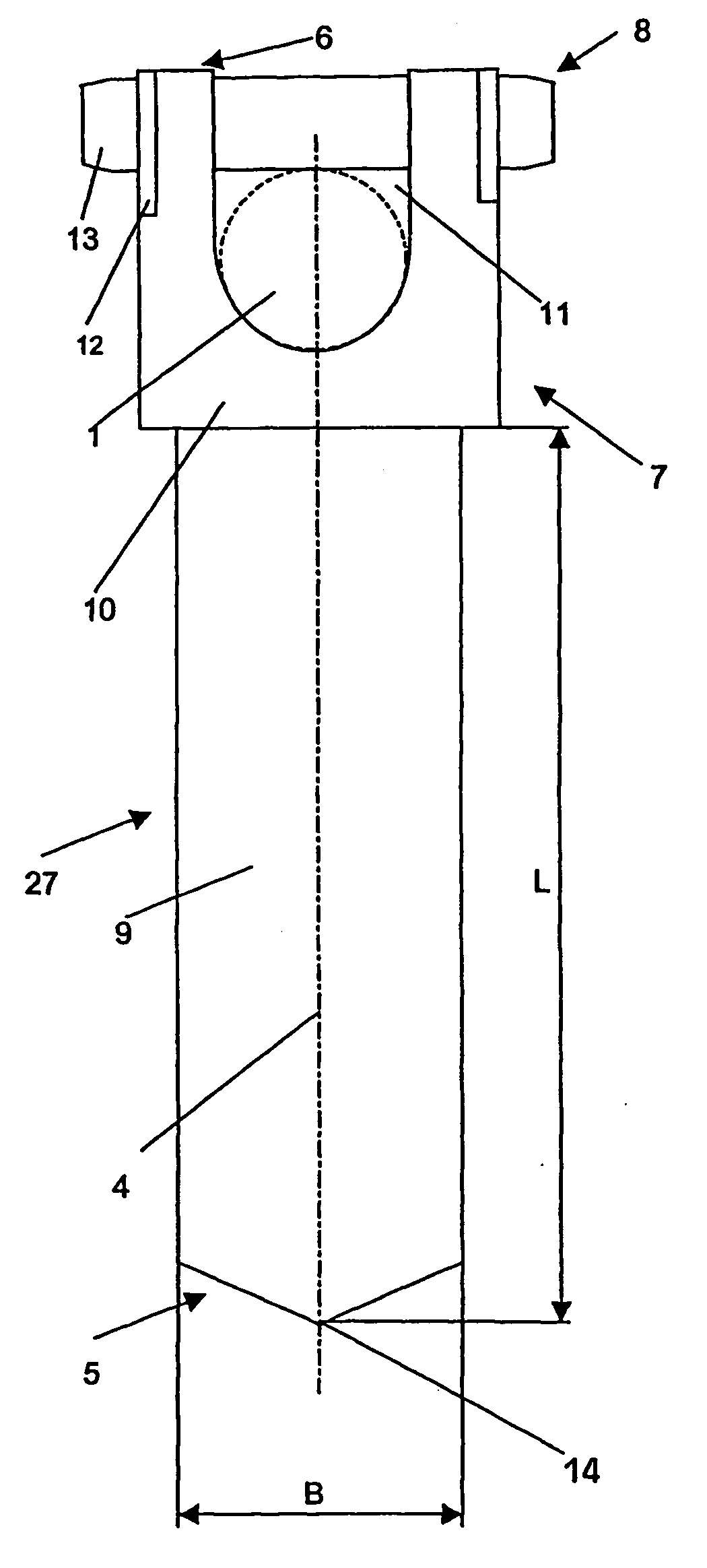
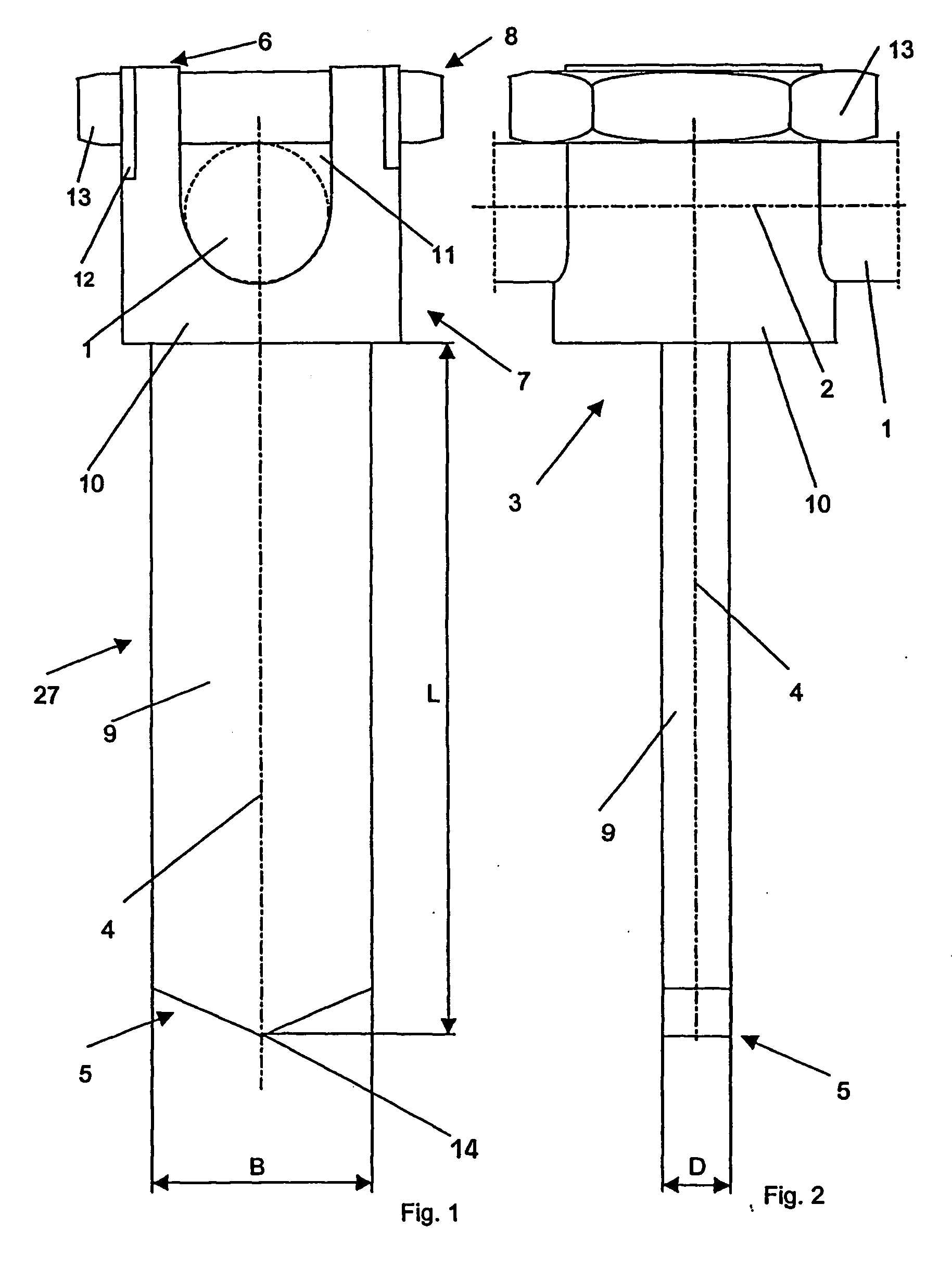
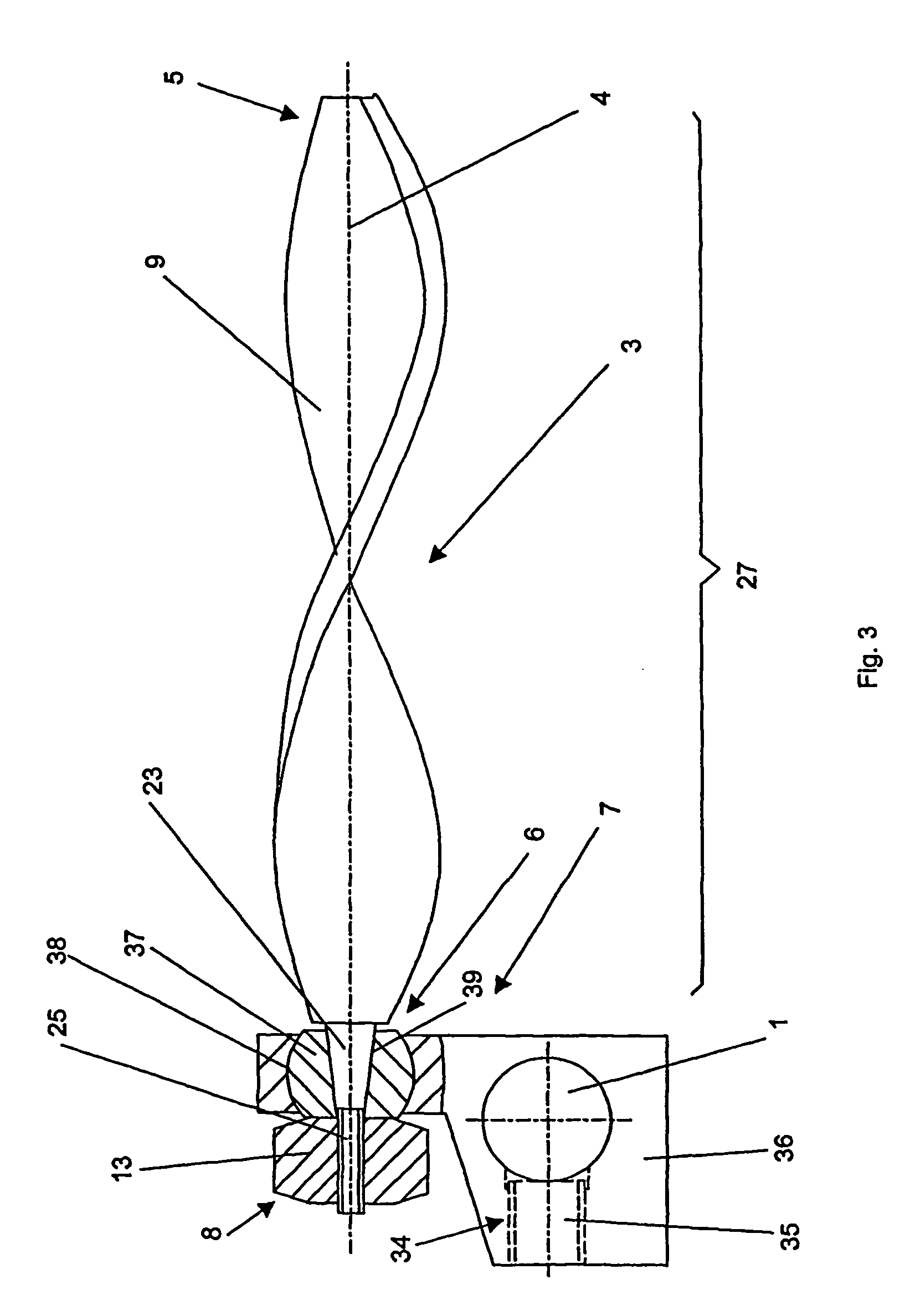
[0030]FIGS. 1 and 2 show an embodiment of the device according to the invention that comprises an anchoring element 3 with receiving means 7 for a longitudinal support 1 at the back end 6 of the anchoring element 3. The receiving means 7 consists of a receiving head 10 that is essentially circular-cylindrical and is coaxial with a longitudinal axis 4 of the anchoring element 3, with a channel 11 that is open toward the back end 6 to receive the longitudinal support 1. In this case, the longitudinal support 1 is received in such a way that its central axis 2 runs vertical to the longitudinal axis 4. In an area between the front end 5 and the receiving head 10, the anchoring element 3 contains an anchoring segment 27, which is designed as an essentially parallelepiped blade 9. Viewed vertically with respect to the longitudinal axis 4, the blade 9 has a rectangular cross-section with a width B and a thickness D. At the front end 5 of the anchoring element 3, the width B of the blade 9 ...


PUM


Abstract

A device for fixation of vertebral bodies including a longitudinal support with a central axis and n anchoring elements (2≦i≦n). Each anchoring element having a longitudinal axes, a front end, and a back end. The longitudinal axis of each anchoring elements may be arranged at an angle of between 65° and 115° relative to the central axis of the longitudinal support, while the anchoring elements are designed to abut the back end. The anchoring elements may be shaped in the form of a blade toward the front end.

Description

CROSS-REFERENCE TO RELATED APPLICATIONS [0001] This application is a continuation of the U.S. national stage designation of copending International Patent Application PCT / CH00 / 00654, filed Dec. 8, 2000, the entire content of which is expressly incorporated herein by reference thereto.FIELD OF THE INVENTION [0002] The present invention relates generally to orthopaedic fasteners, and in particular to a device for fixation of vertebral bodies. BACKGROUND OF THE INVENTION [0003] Instabilities in spinal-column motion segments that may be caused by vertebral fractures, degenerative changes, etc. often require that the segments in question be fused. In order to ensure the immobilization of the segments to be fused as required for bone fusion, the corresponding segments are often stabilized with a fixation system. Fixation systems may either be inserted and anchored from the posterior, whereby the anchoring is done by means of bone screws in the pedicles, or from the anterior or antero-late...

Claims


Application Information

Patent Timeline
Patent Type & Authority Applications(United States)
IPC IPC(8): A61B17/58A61B17/00A61B17/70A61B17/86
CPCA61B17/70A61B2017/00858A61B17/8625A61B17/7025
Inventor SCHLAPFER, FRIDOLINHESS, MARTINTAGWERKER, KONRAD
Owner SYNTHES USA
Why Eureka
Try Eureka