Method of dehumidifying an indoor space using outdoor air

a technology of dehumidification and indoor space, applied in the field of space conditioning systems, can solve problems such as lack of supply of heat supply air

Inactive Publication Date: 2006-12-07
LENNOX MFG
View PDF5 Cites 32 Cited by
  • Summary
  • Abstract
  • Description
  • Claims
  • Application Information

AI Technical Summary

Problems solved by technology

However, there is no provision to heat the supply air in the absence of a demand for heating in the space.

Method used


Image

  • Method of dehumidifying an indoor space using outdoor air
  • Method of dehumidifying an indoor space using outdoor air
  • Method of dehumidifying an indoor space using outdoor air

Examples


Embodiment Construction

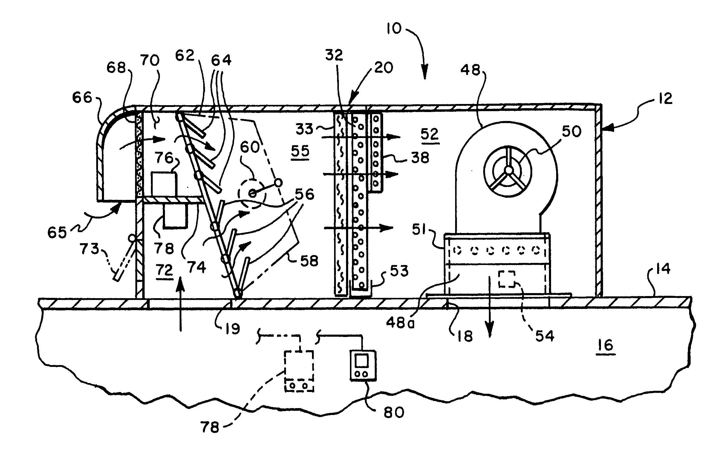
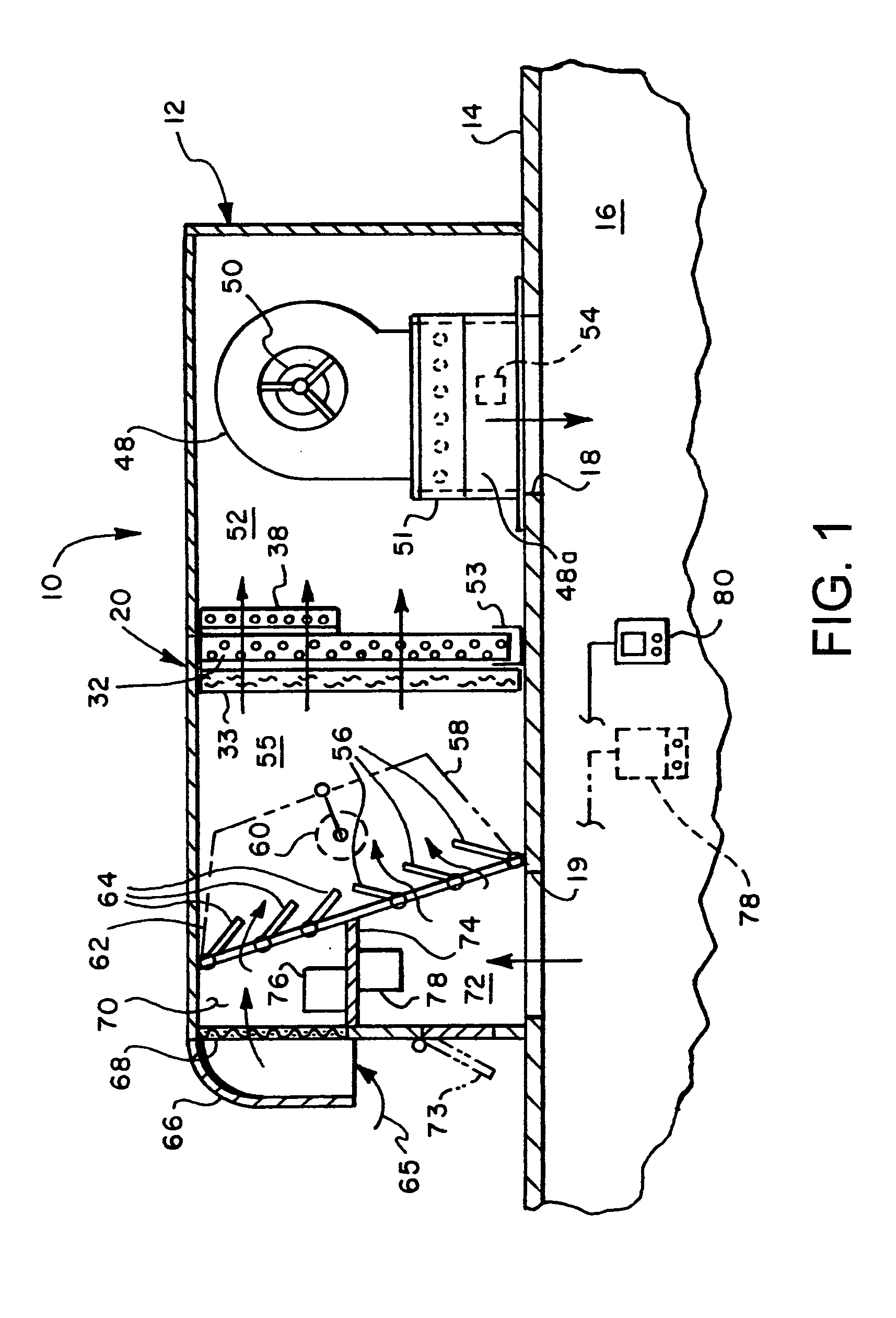
[0012] The best mode for carrying out the invention will now be described with reference to the accompanying drawings. Like parts are marked in the specification and drawings with the same respective reference numbers. In some instances, proportions may have been exaggerated in order to depict certain features of the invention.

[0013] Referring now to FIG. 1, there is illustrated an air conditioning system in accordance with an embodiment of the present invention and generally designated by numeral 10. Air conditioning system 10 is shown, by way of example, as a so-called “rooftop” system having a generally rectangular box-like cabinet 12 adapted to be mounted on a generally horizontal surface such as a rooftop 14. Air conditioning system 10 is adapted to deliver conditioned air to an enclosed space 16 by way of an opening 18 and air within the enclosed space 16 is returned to system 10 by way of an opening 19 to cabinet 12 for conditioning by system 10.

[0014] System 10 preferably ...


PUM


Abstract

A method for dehumidifying air in an indoor space using outside air is comprised of the steps of: sensing whether there is a demand for dehumidification in the space; in response to a demand for dehumidification, determining whether outdoor air is suitable for dehumidification of the space; if the outdoor air is determined to be suitable, admitting outdoor air into the air supplied to the space; and selectively temperature conditioning the supply air in accordance with a predetermined temperature condition therefor. The method is disabled in response to a demand for heating or sensible cooling in the space. Further, the ratio of outdoor air to return air in the supply air is kept relatively constant, irrespective of whether the predetermined temperature condition is satisfied.

Description

TECHNICAL FIELD [0001] This invention relates generally to space conditioning systems for conditioning the temperature and humidity of an indoor space and in particular to a method of dehumidifying the space using outdoor air. BACKGROUND ART [0002] Central air conditioning systems, including systems that use a vapor compression refrigerant to cool air circulated to an indoor space, often require relatively accurate control of humidity in the air within the space. In one such system, as described in U.S. Pat. No. 6,644,049, a reheat heat exchanger is positioned downstream of the system evaporator to reheat air that is cooled and dehumidified by the evaporator. Therefore, dehumidified air can be delivered to the space without appreciably cooling the space. [0003] In the system described in U.S. Pat. No. 6,644,049, outdoor air is not admitted into the system in response to a demand for dehumidification in the space. In the air conditioning system described in U.S. Pat. No. 6,427,461, o...

Claims


Application Information

Patent Timeline
Patent Type & Authority Applications(United States)
IPC IPC(8): F25B49/00F25D17/04
CPCF24F3/153F24F11/0012F24F11/0015F24F2221/34F24F2011/0013F24F2011/0016F24F13/15F24F11/30F24F2110/10F24F2110/12F24F2110/20F24F2110/22F24F11/65
Inventor CAVANAGH, JAMES P.WALTER, STEPHEN A.
Owner LENNOX MFG
Why Eureka
Try Eureka