Recliner drive mechanism for a rocker chair

a drive mechanism and rocker chair technology, applied in dental chairs, medical science, surgery, etc., can solve the problems of complex mechanism with an extremely high number of links and connections, and large number of moving parts

Active Publication Date: 2006-12-07
L & P PROPERTY MANAGEMENT CO
View PDF19 Cites 49 Cited by
  • Summary
  • Abstract
  • Description
  • Claims
  • Application Information

AI Technical Summary

Benefits of technology

[0010] In operation, to move the recliner from the closed, chair position to the open, recliner position, the user rotates a release lever or other activation means rearwardly. The rearward rotation of the lever or other activation means serves to unlock the footrest extension linkage, thereby allowing the weight of the user to move the recliner mechanism from the closed, chair position to the open, recliner position. The unlocking of the footrest extension linkage also allows the drive mechanism to assist in moving the footrest mechanism from the closed, chair position to the open, recliner position. The user may then fully recline the chair by pushing back on the backrest. The rearward force engages the back linkage. This rearward motion of the back linkage engages the lift linkage and drive mechanism and causes the seat to rise. The rearward motion of the back linkage also moves the recliner mechanism from the open, recliner position to the fully-reclined position.

Problems solved by technology

The linkage configurations that are currently in use involve complex mechanisms with an extremely high number of links and connections.
The high number of links and connections results in a drive mechanism with a large number of moving parts.
The high number of moving parts translates into greatly increased maintenance costs and production costs, namely; high machining costs, material costs, and assembly costs.

Method used


Image

  • Recliner drive mechanism for a rocker chair
  • Recliner drive mechanism for a rocker chair
  • Recliner drive mechanism for a rocker chair

Examples


Embodiment Construction

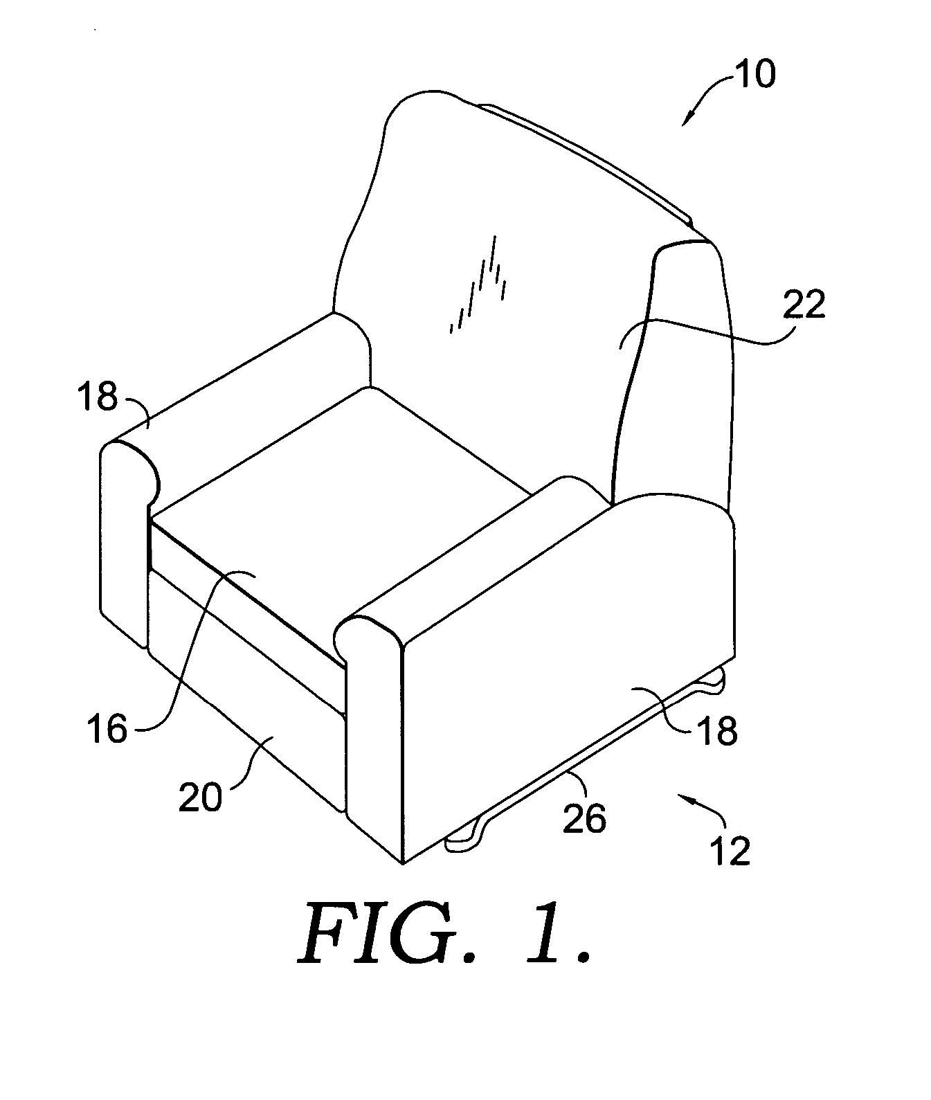
[0023] Referring to the drawings in greater detail and initially to FIG. 1, a rocker recliner chair is shown and designated generally by the numeral 10.

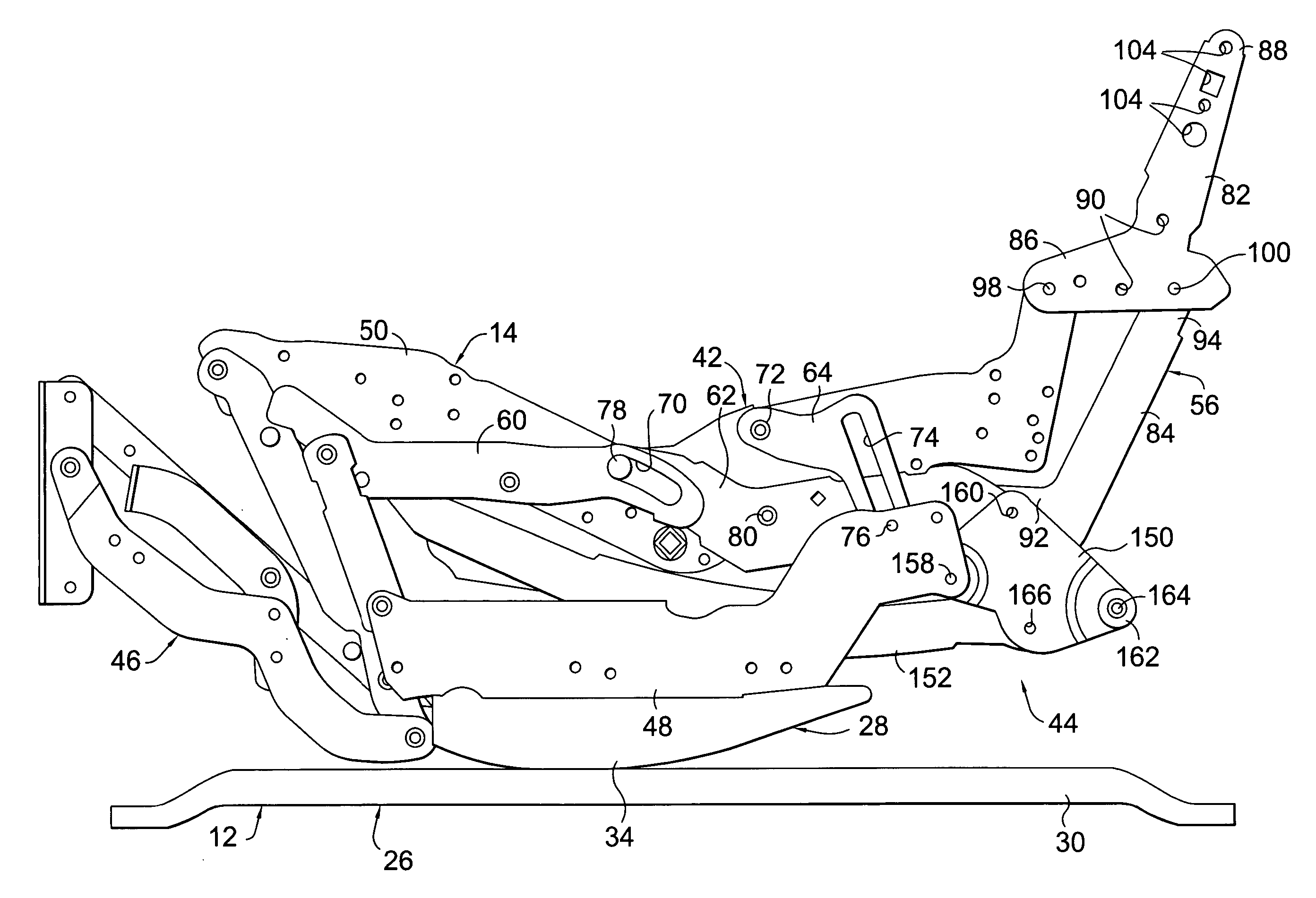
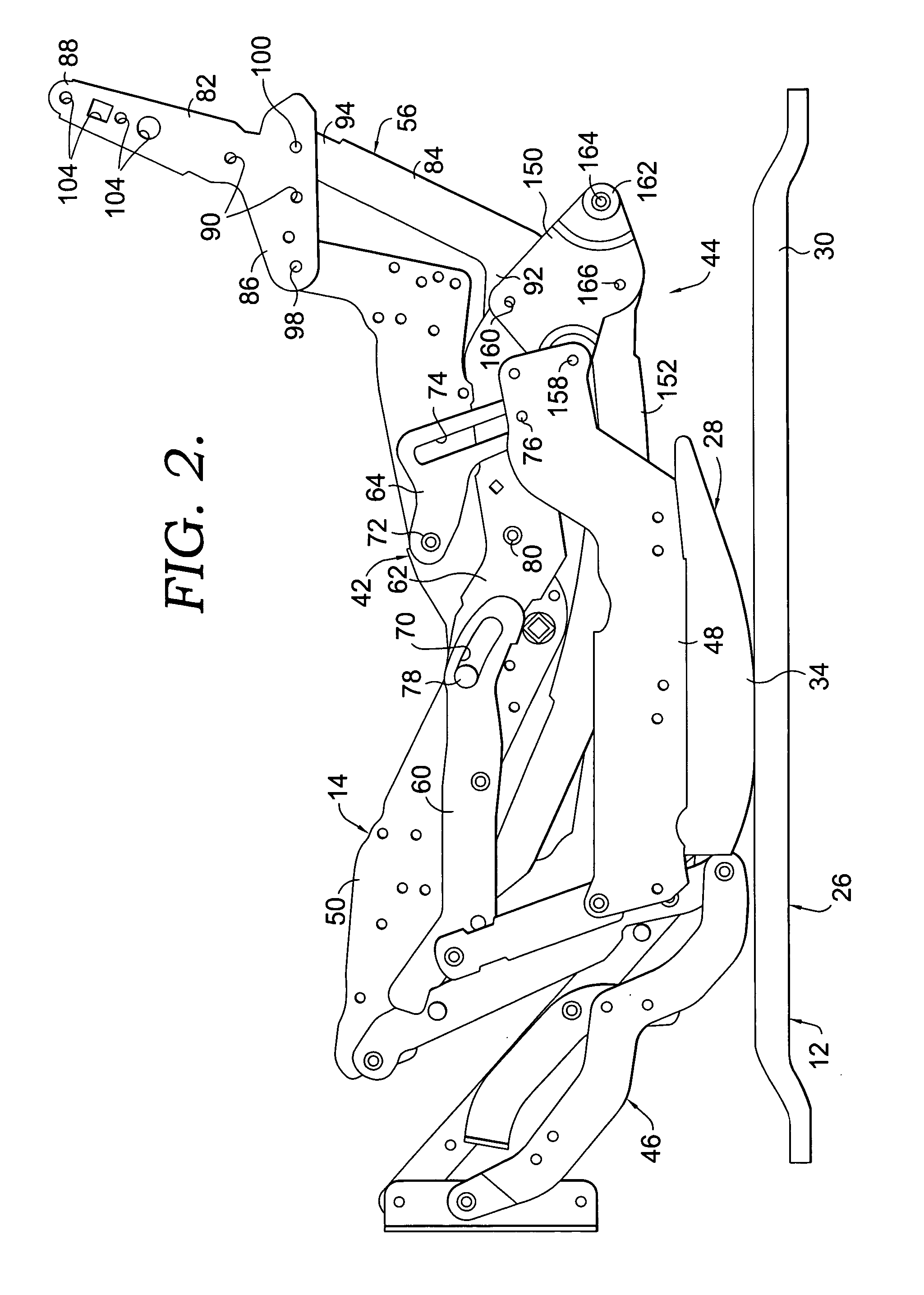
[0024] Generally, as best seen in FIGS. 1 and 2, the chair 10 broadly includes a support frame 12 that provides support for a pair of linkage mechanisms 14 positioned on opposite sides of the chair 10. Linkage mechanisms 14 mount a seat 16, a pair of upstanding opposed armrests 18, a footrest 20 and a backrest 22 to the frame 12 for movement between an upright position as best seen in FIG. 2, an intermediate position as best seen in FIG. 3, and a fully reclined position as best seen in FIG. 4.

[0025] Referring now to FIGS. 2 and 6, the support frame 12 will be discussed. The support frame 12 includes a base 26 and a rocker cam assembly 28. The base 26 includes a pair of side rails 30 positioned on opposite sides of chair 10 and extending between front and rear portions of chair 10. A first pair of cross rails 32 interconnect the sid...


PUM


Abstract

This invention is related to a mechanism for use in a rocker recliner chair that reduces the complexity and links of typical linkage mechanisms. The rocker recliner chair includes a base, a rocker cam assembly mounted on the base, a seat, a footrest, a backrest and a pair of linkage mechanisms mounted on opposite sides of the chair. Each of the linkage mechanisms includes a recliner mechanism, a drive mechanism, and a footrest mechanism. The recliner mechanism is coupled to the base. The drive mechanism includes an ottoman drive bell crank and an ottoman drive link. The ottoman drive bell crank is coupled to a rear portion of the recliner mechanism. The ottoman drive link couples the ottoman drive bell crank to the footrest mechanism. The footrest mechanism is connected to the recliner mechanism by a footrest extension linkage. The footrest extension linkage serves to unlock the footrest mechanism thereby allowing the weight of the user, along with the drive mechanism, to move the chair from the chair position to the recliner position.

Description

CROSS-REFERENCE TO RELATED APPLICATIONS [0001] Not applicable. STATEMENT REGARDING FEDERALLY SPONSORED RESEARCH OR DEVELOPMENT [0002] Not applicable. BACKGROUND OF THE INVENTION [0003] This invention relates to a recliner mechanism for a rocker recliner chair, and more particularly to a drive mechanism for a rocker recliner chair that is capable of moving the chair from a closed position to an open, reclined position, then to a fully reclined position. [0004] Rocker recliners are generally well known in the furniture industry. Typically, rocker recliners are chairs with extendable footrests that allow the user to recline. Rocker recliner chairs usually contain a linkage mechanism comprised of a footrest mechanism, a recliner mechanism, and a drive mechanism. A rocker recliner chair typically has three positions in use: a closed, stowed position, an open, reclining position, and a fully-reclined position. The drive mechanism operates to move the footrest mechanism and the recliner me...

Claims


Application Information

Patent Timeline
Patent Type & Authority Applications(United States)
IPC IPC(8): A47C1/02
CPCA47C1/0355
Inventor WHITE, NIKKITACKER, BILL D.JOHNSON, TERRY D.
Owner L & P PROPERTY MANAGEMENT CO
Why Eureka
Try Eureka