RFID tag with separate transmit and receive clocks and related method

a technology of transmit and receive clock and rfid tag, which is applied in the field of wireless systems, can solve the problems of tag not being able to respond to interrogation, unable to power tag, and limited maximum distance by actual power consumption of rfid tag,

Inactive Publication Date: 2006-12-07
INTEL CORP
View PDF7 Cites 122 Cited by
  • Summary
  • Abstract
  • Description
  • Claims
  • Application Information

AI Technical Summary

Problems solved by technology

Because the RFID tag is powered solely by the interrogation signal, the maximum distance is limited by the actual power consumption of the RFID tag.
Eventually, a distance will be reached where it is no longer possible for the tag to power on because there is not enough energy available and hence the tag will be unable to respond to the interrogation.

Method used


Image

  • RFID tag with separate transmit and receive clocks and related method
  • RFID tag with separate transmit and receive clocks and related method
  • RFID tag with separate transmit and receive clocks and related method

Examples


Embodiment Construction

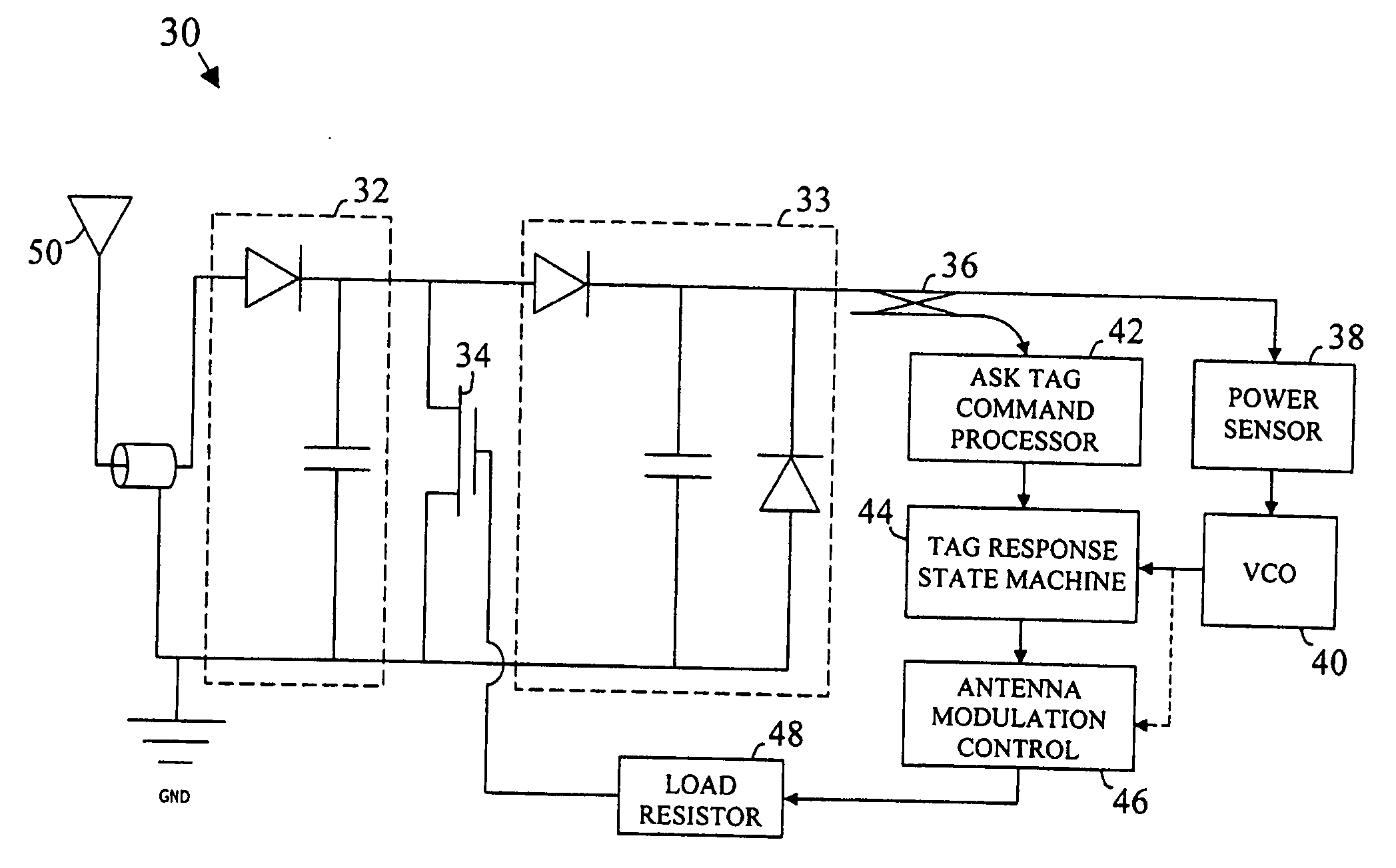
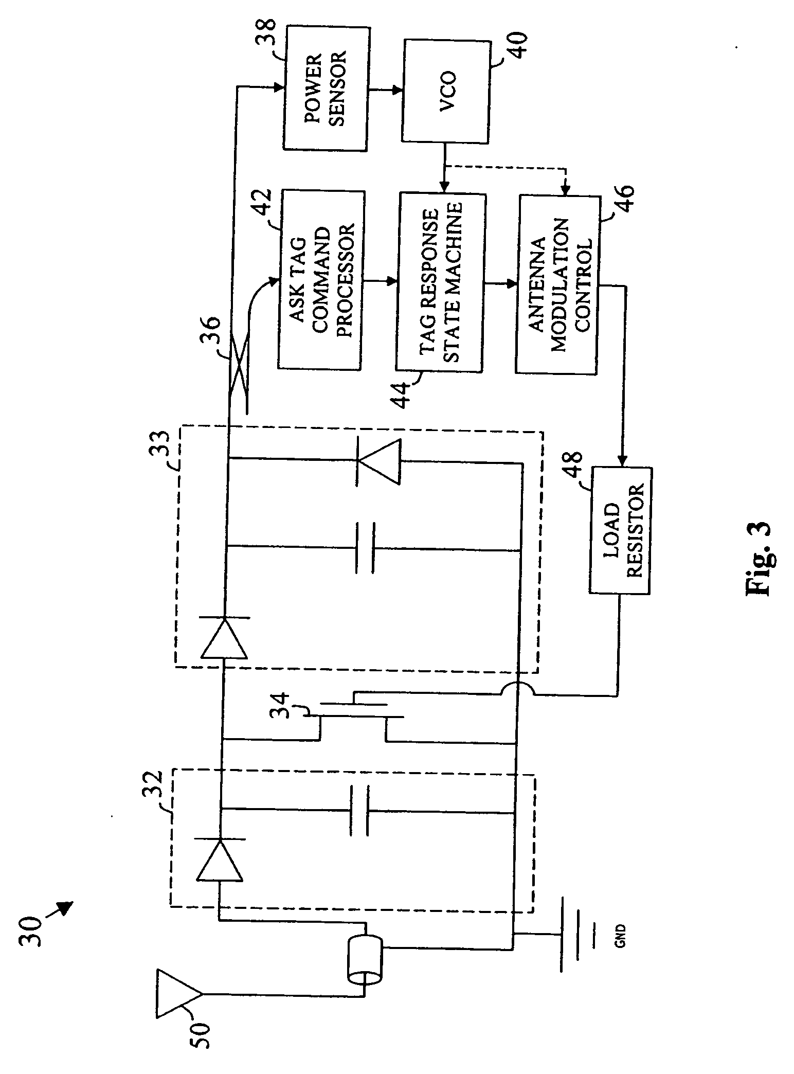
[0008] In the following detailed description, reference is made to the accompanying drawings that show, by way of illustration, specific embodiments in which the invention may be practiced. These embodiments are described in sufficient detail to enable those skilled in the art to practice the invention. It is to be understood that the various embodiments of the invention, although different, are not necessarily mutually exclusive. For example, a particular feature, structure, or characteristic described herein in connection with one embodiment may be implemented within other embodiments without departing from the spirit and scope of the invention. In addition, it is to be understood that the location or arrangement of individual elements within each disclosed embodiment may be modified without departing from the spirit and scope of the invention. The following detailed description is, therefore, not to be taken in a limiting sense, and the scope of the present invention is defined o...


PUM


Abstract

An RFID tag includes separate transmit and receive clocks. In at least one embodiment, the transmit clock frequency is adjusted based on an amount of power available to transmit a response signal to a reader.

Description

TECHNICAL FIELD [0001] The invention relates generally to wireless systems and, more particularly, to radio frequency identification (RFID) structures and techniques. BACKGROUND OF THE INVENTION [0002] An RFID tag is a radio frequency (RF) transponder device that is designed to respond to the receipt of an interrogation signal from an RFID reader device by communicating information back to the reader device. RFID tags are currently used in a wide variety of applications including, for example, pallet tracking, inventory tracking, airport baggage tracking, tracking of pets, item identification, personnel identification (e.g., ID badges), and many others. RFID tags typically fall into two categories; namely, passive tags and active tags. An active RFID tag includes a power source (e.g., a battery, etc.) to power the circuitry therein. A passive RFID tag, on the other hand, does not include a power source. Instead, the passive RFID tag derives its operation power from the interrogation...

Claims


Application Information

Patent Timeline
Patent Type & Authority Applications(United States)
IPC IPC(8): H04Q5/22
CPCG06K19/0723
Inventor POSAMENTIER, JOSHUA
Owner INTEL CORP
Why Eureka
Try Eureka