
Droplet ejecting apparatuses and methods for cleaning droplet ejecting face and wiping member

a technology of dropping and ejecting face, which is applied in the direction of printing, etc., can solve the problems of ink ejection, droplet ejection face, ink leakage from the nozzle, bounce back from the recording sheet, etc., and achieve the effect of stabilizing the efficiency of the cleaning of the droplet ejecting face, preventing destabilizing the direction of the ejection, and simple structure for moving the cleaning member

Inactive Publication Date: 2006-12-07
FUJIFILM BUSINESS INNOVATION CORP
View PDF3 Cites 17 Cited by
  • Summary
  • Abstract
  • Description
  • Claims
  • Application Information

AI Technical Summary

Benefits of technology

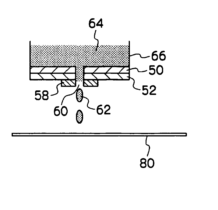
[0019] When the droplet ejecting apparatus is operated and droplets containing a resin are ejected, the adhesion of the ink to near the nozzle is prevented owing to the presence of the water-shedding film and dirt accumulates the hydrophilic film provided around the water-shedding film. The dirt is decomposed upon irradiation with light owing to the action of the photocatalyst contained in the hydrophilic film. Therefore, the dirt does not remain on the hydrophilic film or is easily removable by wiping or the like. Since dirt does not deposit on the droplet ejecting face even when ejection is conducted for a long time, stable ejection can be achieved and the lifetime of the droplet ejection unit is elongated.
[0039] The recording liquid may comprise a resin. When the recording liquid containing the resin is used, dirt is likely to adhere to the droplet ejecting face of the droplet ejecting unit. The direction of the ejection of the recording liquid is maintained stable by the stable cleaning of the droplet ejecting face.

Problems solved by technology

However, pigments themselves do not strongly adhere to the recording sheets.
However, ink leaks from the nozzles and also bounces back from the recording sheet during printing.
However, even when this method is used, resin deposition occurs near the nozzles, the ejection of ink is impaired, and the directivity of the ink ejection is deteriorated during long-term use.
However, when hydrophilicity is imparted to near the nozzles such as the nozzle sheet, ink leaks more easily to destabilize the formation of ink meniscus which largely affects the ejection of ink droplets.
Particularly when the head structure adopts droplet modulation using the control of ink meniscus by a piezoelectric element or the like, the stability of the ejection is adversely affected.
Further, when the droplet ejection quantity is large, such as in the case of a printer equipped with the full-line head having plural ejection openings along the entire width of the recording region or in the case of high-speed printing in large quantity, the effect brought about by the technique is insufficient.
Therefore, the problems concerning ink dirt have not been solved.
However, the inks are disadvantageous in the fixability of the image and the resistance to rubbing.
When such an ink are used, the ink leaks from the nozzles and also bounces back from the recording sheet during printing to adhere to near the nozzles.
The deposition of the ink destabilize ink meniscus and deteriorates the directivity of the ejection of ink droplets.
However, when this method is used, the resin deposits also on the blade during long-term use.
As a result, the cleaning performance of the blade is deteriorated, so that the blade is no longer able to completely remove the resin or the like deposited on near the nozzles.
Therefore, the directivity of the ejection of ink droplets is deteriorated.
However, sucked dirt accumulates in the sucking device in long-term use, whereby the suction efficiency of the suction device is lowered.
Therefore, the dirt adhered to the blade cannot be completely removed by this method, either.

Method used


Image

  • Droplet ejecting apparatuses and methods for cleaning droplet ejecting face and wiping member
  • Droplet ejecting apparatuses and methods for cleaning droplet ejecting face and wiping member
  • Droplet ejecting apparatuses and methods for cleaning droplet ejecting face and wiping member

Examples


example 2

[0189] In order to determine the minimum required thickness of the titanium oxide film, an evaluation test is conducted under the following conditions.

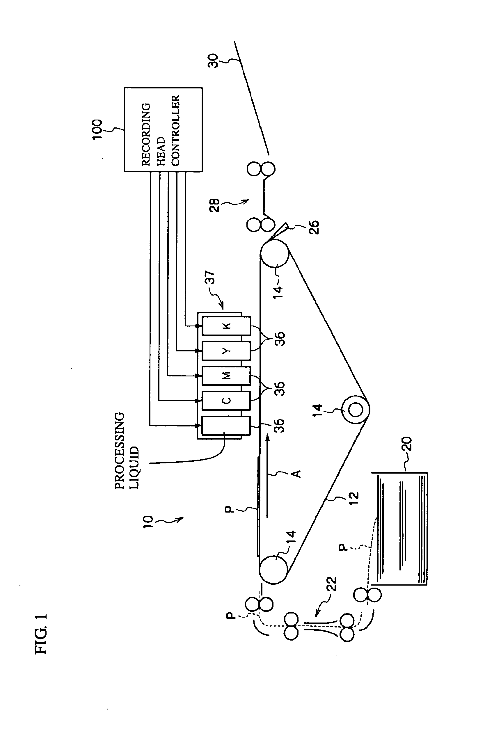
[0190] Printing is conducted using an inkjet recording apparatus equipped with an experimental recording head having 256 nozzles capable of ink ejection at 400 dpi with the driving frequency of the piezoelectric element of the recording head set at 9 kHz. Every time printing on 25 sheets P is completed, cleaning device 140 is operated, blade 142 wipes nozzle face 120A of recording head 120, and wiping part 172 of wiping member 170 wipes off the ink adhered to blade 142.

[0191] The graph of FIG. 9 shows the relationship between cumulative printed dots per one nozzle and deviation of the ink deposition point on sheet P in each of the cases of titanium coatings respectively with thicknesses of 0.5 μm and 5 μm provided on wiping part 172 of wiping member 170.

[0192] Sensory evaluation is conducted every time the cumulative printed dots r...


PUM


Abstract

A droplet ejecting apparatus comprising a droplet ejecting unit having a droplet ejecting face, wherein the droplet ejecting face is provided with nozzles which eject droplets containing an organic compound, the droplet ejecting apparatus ejects the droplets by an inkjet method, the droplet ejecting apparatus comprises a water-shedding film provided on the droplet ejecting face near the nozzles and a hydrophilic film containing a photocatalyst provided in a region on the droplet ejecting face other than near the nozzles. Also provided is a droplet ejecting apparatus comprising a droplet ejecting unit, a cleaning member, and a wiping member, wherein the cleaning member removes the dirt containing an organic compound adhered to the droplet ejecting face, the wiping member wipes off the dirt containing the organic compound adhered to the cleaning member, and a wiping part of the wiping member comprises a photocatalyst.

Description

CROSS-REFERENCE TO RELATED APPLICATION [0001] This application claims priority under 35 USC 119 from Japanese patent Application Nos. 2005-166863 and 2005-181638, the disclosures of which are incorporated by reference herein. BACKGROUND OF THE INVENTION [0002] 1. Field of the Invention [0003] The present invention is related to droplet ejecting apparatuses which conduct recording by ejecting droplets from droplet ejecting units to recording media, methods for cleaning droplet ejecting faces, and methods for cleaning wiping members mounted on droplet ejecting apparatuses. [0004] 2. Description of the Related Art [0005] Droplet ejecting apparatuses which eject liquid ink from ejection openings, in particular inkjet recording apparatuses, have been uses as engines for many image forming systems recently because they are compact and inexpensive. Recording heads using piezoelectric systems (piezo-inkjet systems) are often used in inkjet printers because of their capability of forming hig...

Claims


Application Information

Patent Timeline
IPC IPC(8): B41J2/155
CPCB41J2/155B41J2002/16502B41J2/16535B41J2/1606B41J2/16502
Inventor ONO, YOSHIHIKO
Owner FUJIFILM BUSINESS INNOVATION CORP
Learn More