Kitchen appliances with speed control

a technology of speed control and kitchen appliances, which is applied in the field of kitchen appliances having a speed adjustment function, can solve the problems of affecting the accuracy of the device, the amount of movement of the input switch of a hand-held device such as a bar blender, and the inability to adjust the speed of the device, so as to achieve the effect of easy and comfortable use, greater control of the speed

Active Publication Date: 2016-09-08
VERSUNI HLDG BV
View PDF7 Cites 6 Cited by
  • Summary
  • Abstract
  • Description
  • Claims
  • Application Information

AI Technical Summary

Benefits of technology

[0022]The appliance can further comprise a tactile, audible or visual feedback system for providing feedback during button movement. This gives the user greater control of the speed.
[0023]Preferably, the power switch is mechanically actuated within 3 mm of movement of the button from An initial button position, and more preferably within 2 mm of movement of the button from the initial position. This provides a short movement distance before the speed adjustment function is enabled.
[0024]The movement of the button can be limited to at most 20 mm, more preferably at most 10 mm. This means the full control is achieved within a short range of movement, which is found to provide an interface which is easiest and most comfortable for the user.

Problems solved by technology

However, this is inconsistent with the requirement for separate circuits.
Furthermore, the amount of movement of the input switch for a hand held device such as a bar blender is limited since the whole device is gripped in the palm of the hand.
In particular, a push switch should have a short path of movement, since long movement paths are associated by customers with low quality, and they also hamper accurate operation of the device.

Method used


Image

  • Kitchen appliances with speed control
  • Kitchen appliances with speed control
  • Kitchen appliances with speed control

Examples


Embodiment Construction

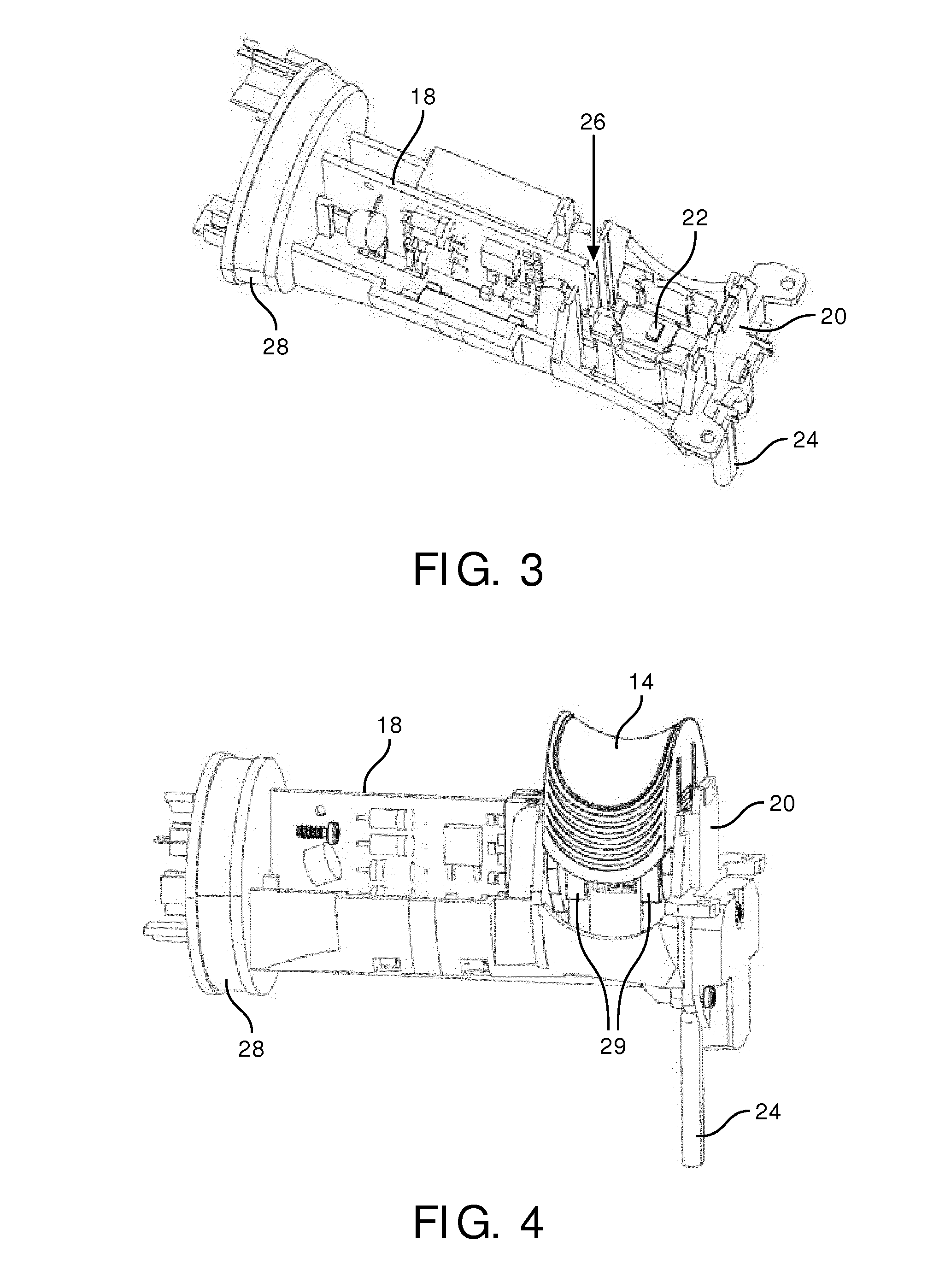
[0043]The invention provides a kitchen appliance having a power switch for controlling supply of power to a motor and a separate control circuit for controlling the speed. A button for control by the user is provided for controlling the actuation and speed. A carrier carries the button, and also carries a first actuator for mechanically actuating the power switch when the button is first moved. When the button is further moved, the motor speed is controlled.

[0044]This provides a one-button solution, combining the power on / off function and the speed adjustment in one switch, and which can be designed with a minimum length of travel of the button.

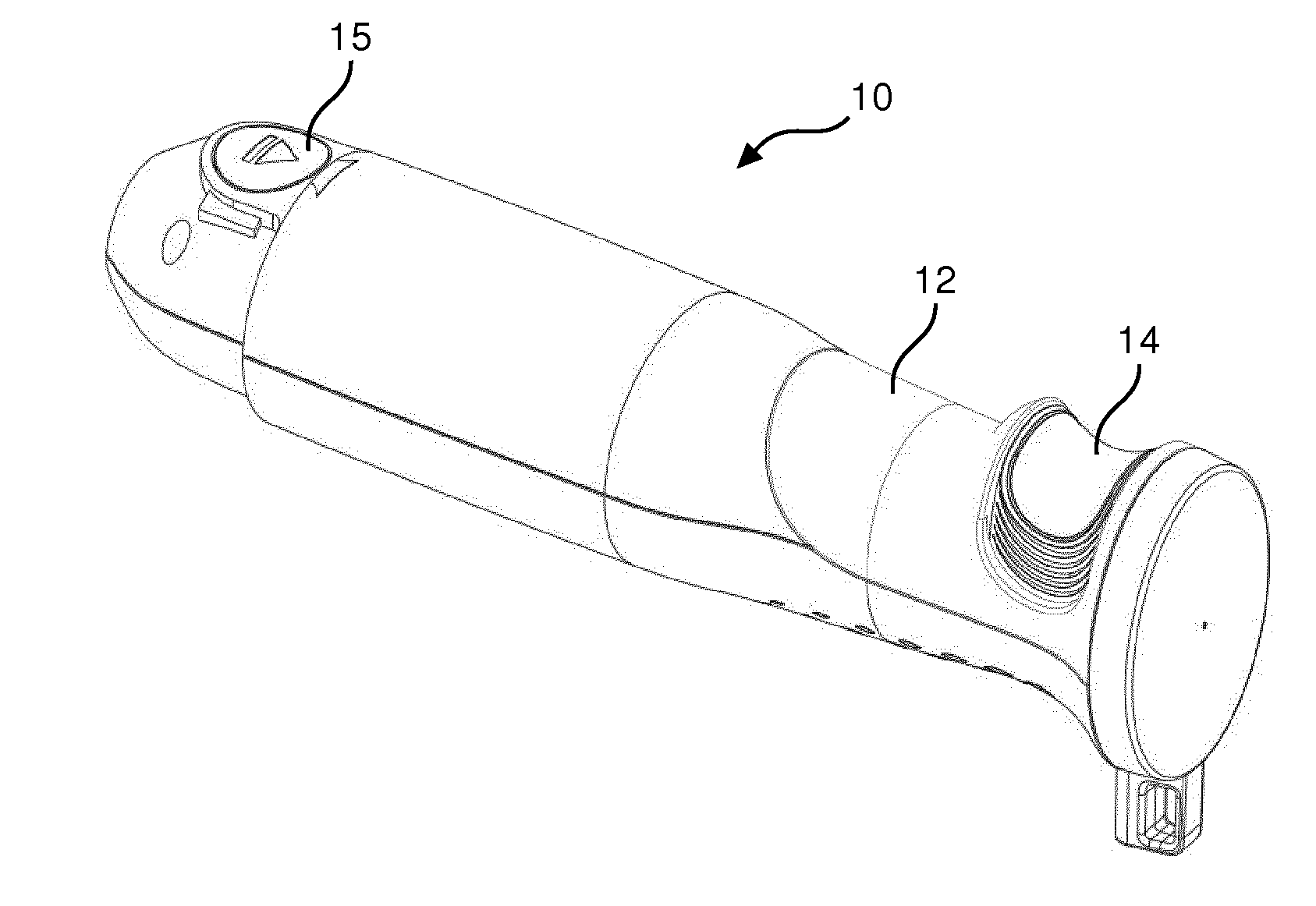
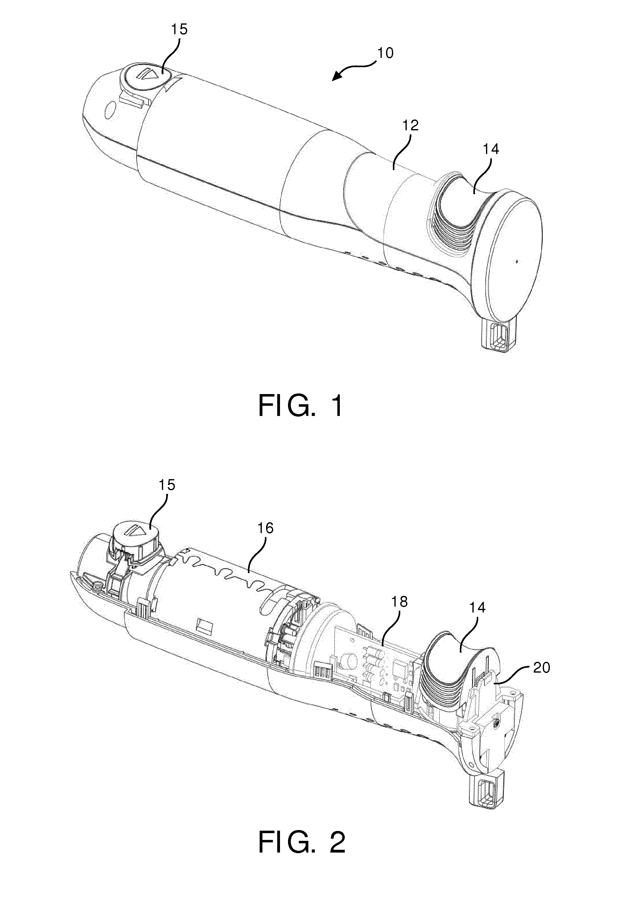
[0045]Detailed examples will now be described, which show the invention applied to a bar blender having a push button control input. The same switch design can however be applied to other kitchen appliances and with other configurations of dual function button.

[0046]FIG. 1 shows a first example of bar blender using the switch arrangement of t...


PUM


Abstract

A kitchen appliance has a power switch for controlling supply of power to a motor and a separate control circuit (18) for controlling the speed. A button (14) for control by the user is provided for controlling both the actuation and speed. A carrier (40) carries the button, and also carries a first actuator (44,86) for mechanically actuating the power switch when the button is first moved. When the button is further moved, the motor speed is controlled.

Description

FIELD OF THE INVENTION[0001]This invention relates to kitchen appliances having a speed adjustment function. One example is bar blenders.BACKGROUND OF THE INVENTION[0002]According to regulations it is required to separate power supply circuits and control circuits in kitchen devices. For this reason, current kitchen appliances such as bar blenders have a user interface which provides galvanic separation of power control and speed adjustment. Thus, bar blenders typically have an on-off control switch, and a separate speed control input. There are various ways to implement the user interface to provide an easy to use device.[0003]A first known approach is to provide a speed pre-selection switch and a separate push type on / off switch, which needs to be held on. The speed is pre-selected before the rotation of the tool is activated by pressing the on / off-switch. Some devices comprise an additional turbo switch to boost the speed.[0004]A second known approach is to provide an on / off swit...

Claims


Application Information

Patent Timeline
Patent Type & Authority Applications(United States)
IPC IPC(8): A47J43/08
CPCA47J2043/04427A47J43/082A47J43/08
Inventor PLANEGGER, WALTER ALEXHOSNER, MARIODERMOL, JOZE
Owner VERSUNI HLDG BV
Why Eureka
Try Eureka