System and method for detecting back electromotive force with automatic pole calibration

a back electromotive force and automatic pole calibration technology, applied in the direction of motor/generator/converter stopper, dynamo-electric converter control, electric controller, etc., can solve the problems of power consumption, chip noise, supply current spike, etc., and achieve accurate detection of back electromotive force voltage

Inactive Publication Date: 2008-06-10
MARVELL ASIA PTE LTD
View PDF33 Cites 8 Cited by
  • Summary
  • Abstract
  • Description
  • Claims
  • Application Information

AI Technical Summary

Benefits of technology

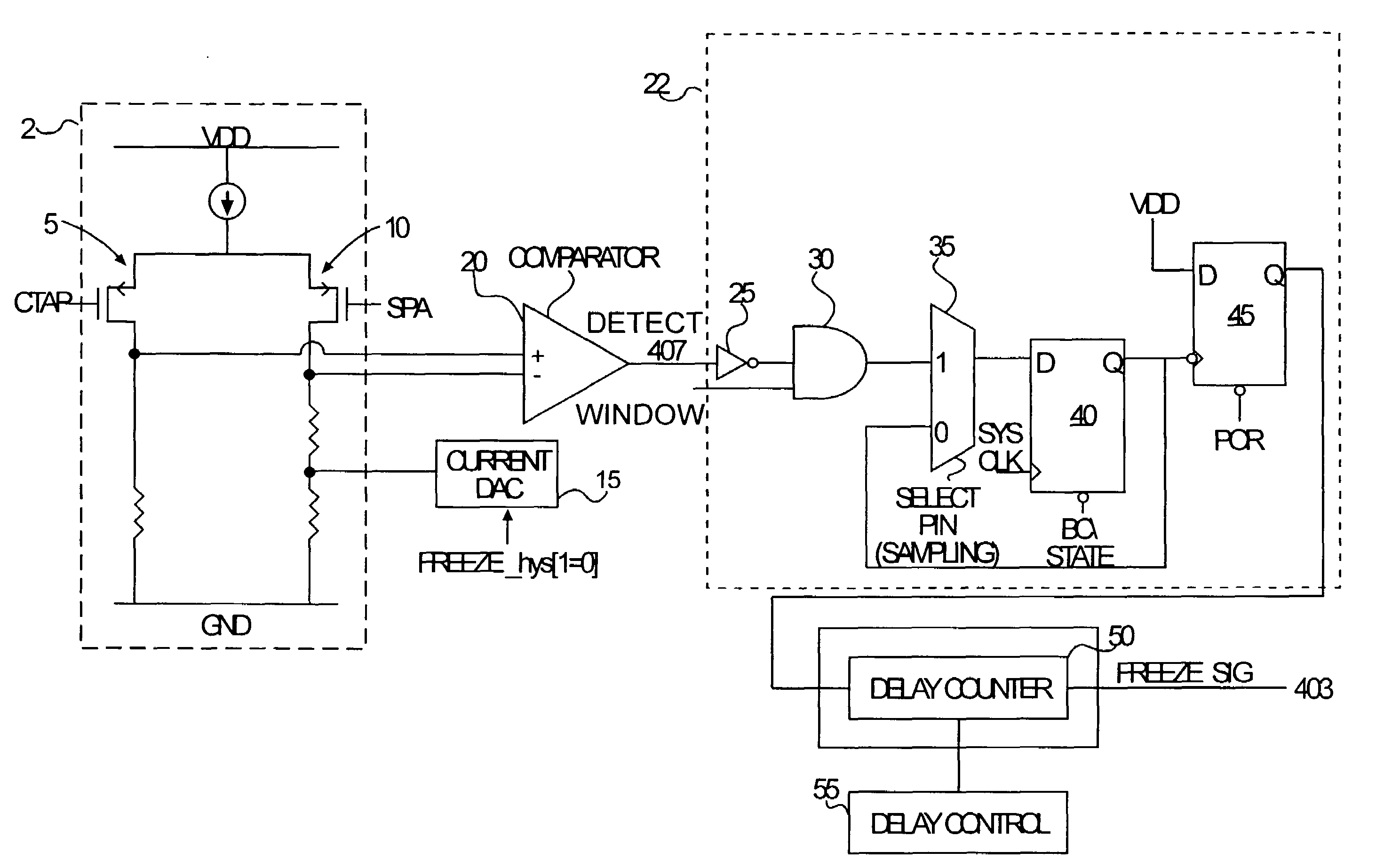
[0020]The invention avoids the disadvantages and drawbacks of the prior art and / or satisfies the need for more accurately detecting back electromotive force voltage from a motor, such as a disk drive.
[0021]The invention thus provides a system and process for detecting back electromotive to detect poles in a motor while improving consistency and reducing the amount of time a freeze signal is used.
[0022]The advantages of the invention include the ability to control the width of the freeze signal more accurately, the speed control of the system may be improved and the width (time) of the freeze signal also may be minimized to a small value, thereby saving power as well as reducing acoustic noise. Advantages may also be achieved in the circuitry required to implement the BEMF detection methods of the invention as fewer gates and less silicon chip space are required than with prior known detection methods.

Problems solved by technology

This method of BEMF detection suffers from a number of deficiencies.
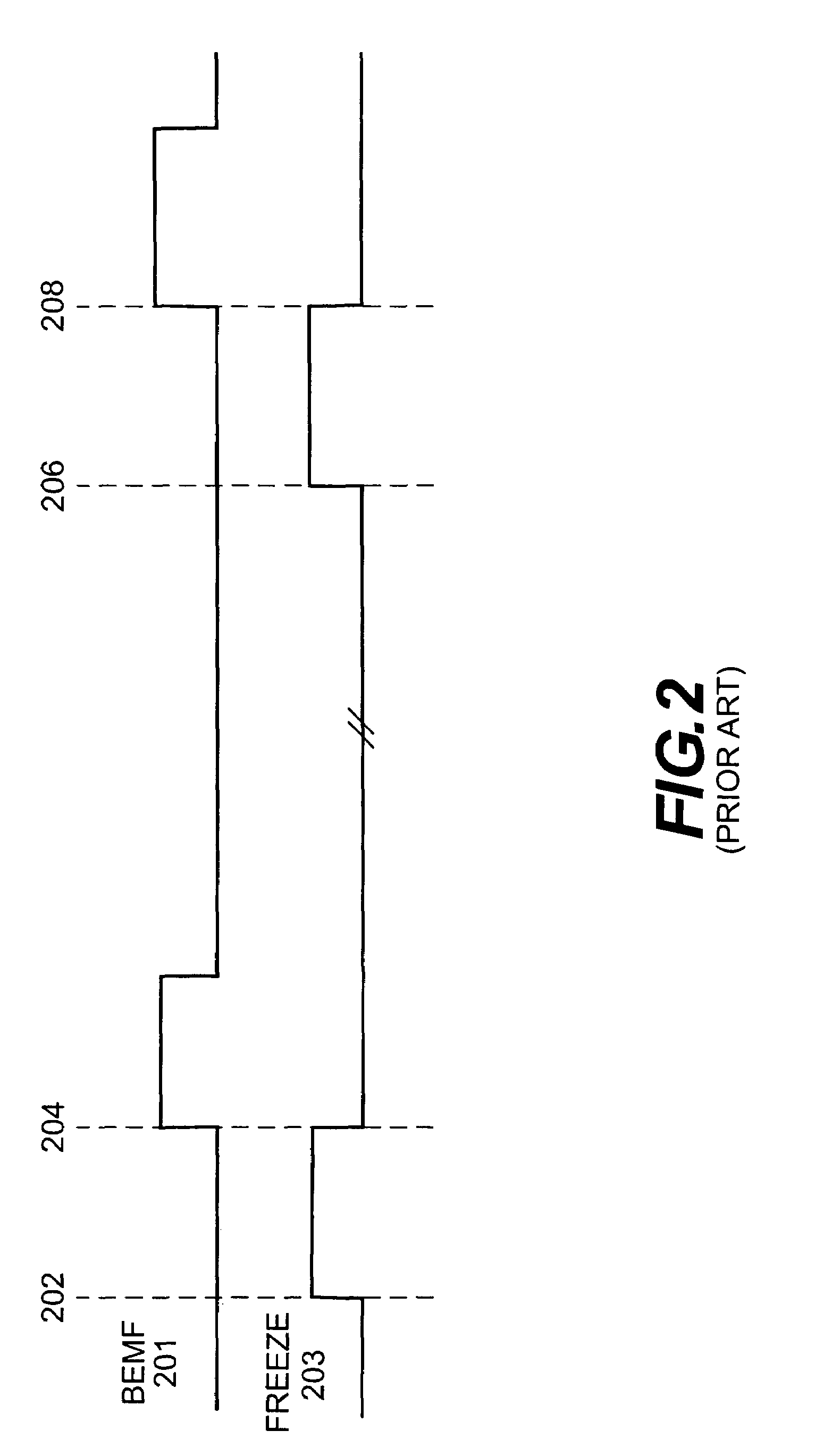
One problem is that during the time period when the freeze signal is generated, the supply current will spike due to the freeze signal pulling the driver(s) to a high voltage level.
This spiking will contribute to power consumption as well as noise in the chip.
A further problem with this method arises because the poles for the motor that rotates the media may be unequally spaced apart from each other.
This results in some differences between the expected position and the actual position of different poles.
As described previously, a freeze signal that is too long may result in a current surge in the power supply, thereby draining the power supply.
Further, a surge in current can cause the motor to accelerate, thereby increasing the speed of rotation.
This can be problematic for some applications where the speed of the motor needs to be kept relatively constant, such as in disk drives.
This may disrupt the proper use and / or functioning of the motor, which may require very precise operation, such as when used to rotate the data media in a disk drive.

Method used


Image

  • System and method for detecting back electromotive force with automatic pole calibration
  • System and method for detecting back electromotive force with automatic pole calibration
  • System and method for detecting back electromotive force with automatic pole calibration

Examples


Embodiment Construction

[0037]The embodiments of the invention and the various features and advantageous details thereof are explained more fully with reference to the non-limiting embodiments and examples that are described and / or illustrated in the accompanying drawings and detailed in the following description. It should be noted that the features illustrated in the drawings are not necessarily drawn to scale, and features of one embodiment may be employed with other embodiments as the skilled artisan would recognize, even if not explicitly stated herein. Descriptions of well-known components and processing techniques may be omitted so as to not unnecessarily obscure the embodiments of the invention. The examples used herein are intended merely to facilitate an understanding of ways in which the invention may be practiced and to further enable those of skill in the art to practice the embodiments of the invention. Accordingly, the examples and embodiments herein should not be construed as limiting the s...


PUM


Abstract

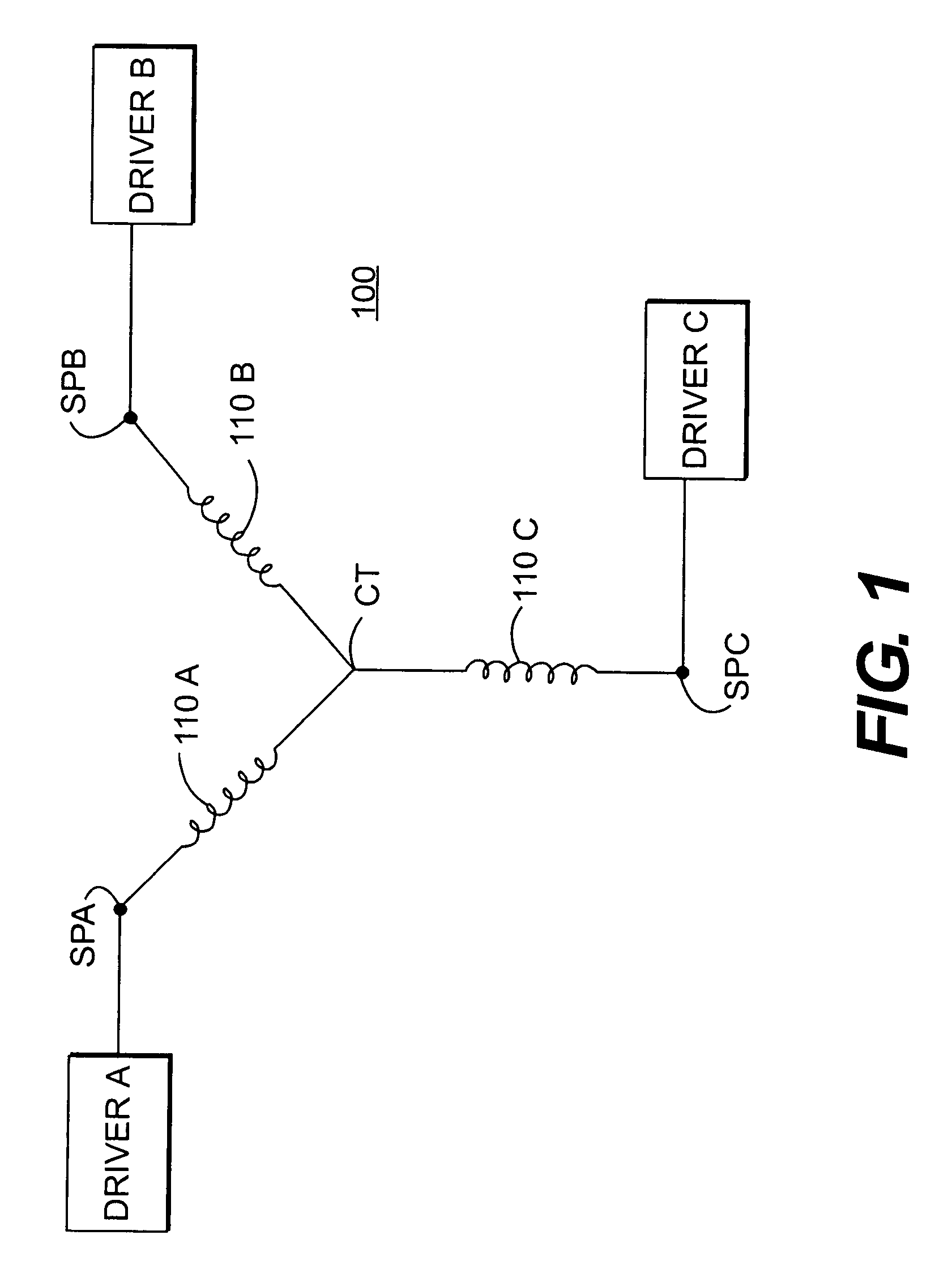
A system and method for determining the rotational speed of a motor, such as a three-phase disk drive motor, detects back electromotive force voltage generated during operation of the motor with an automatic pole calibration to minimize or eliminating variations in the wave of a freeze signal. A phase voltage at a winding is compared against a center tap (CT) voltage. Once the phase voltage falls to a specified voltage level, a detect signal is generated. A predetermined time after the detect signal is generated, a freeze signal is generated for freezing at least the circuit associated with the winding.

Description

CROSS REFERENCE TO RELATED APPLICATIONS[0001]This application claims priority under 35 U.S.C. § 120 to U.S. application Ser. No. 11 / 180,651, filed on Jul. 14, 2005, which claims priority under 35 U.S.C. §119(e) to U.S. Provisional Application Ser. No. 60 / 651,880, filed on Feb. 9, 2005, the disclosures of which are both expressly incorporated by reference herein in their entireties.BACKGROUND OF INVENTION[0002]1. Field of Invention[0003]The invention relates to a system and method for detecting electromotive force and, more particularly, to a system and method for detecting back electromotive force voltage in electric motors, such as disk drives, with an automatic pole calibration which can be used to sense the rotational speed of the motor or, in a disk drive, the speed of the media rotated by the motor.[0004]2. Related Art[0005]Motors used in disk drives, such as spindle motors, can be three phase motors which include a rotor having permanent magnets and a stator having windings fo...

Claims


Application Information

Patent Timeline
Patent Type & Authority Patents(United States)
IPC IPC(8): H02P25/08H02P3/08
CPCH02P6/182
Inventor HOO, LEGAL REPRESENTATIVE, KUONGLEONG, FOO LENGCHUI, SIEW YONGTEOH, CHENG YONGRANA, SAKTI PADA
Owner MARVELL ASIA PTE LTD
Why Eureka
Try Eureka