Interferometer Velocity Control of Beamsplitter and Moving Mirrors

a technology of interferometer and beam splitter, which is applied in the field of optical scientific instruments, can solve the problems of degraded response time, added velocity error noise, and often limited performance, and achieves the effects of compact light weight, reduced response time, and reduced error ra

Active Publication Date: 2012-05-17
THERMO ELECTRONICS SCI INSTR LLC
View PDF0 Cites 8 Cited by
  • Summary
  • Abstract
  • Description
  • Claims
  • Application Information

AI Technical Summary

Benefits of technology

[0011]Another aspect of the present invention provides for a dynamic long-stroke velocity controlled interferometer that includes: a moving first plane reflector configured to respectively receive and return a first portioned beam of a source along a first optical path length, wherein the moving first plane reflector is coupled to a moving bearing assembly configured to position the front surface of the first plane reflector substantially perpendicular along a longitudinal axis of the moving bearing assembly; a second plane reflector configured to respectively receive and return a second portioned beam of the source along a second optical path length; a moving beam splitter for receiving a beam of radiation from the source so as to provide the first and the second portioned beams; wherein the moving beam splitter is further adapted to move linearly in a direction toward and away but at a predetermined angle to the configured first and second plane reflectors; movement means coupled to the moving beam splitter to provide linear and tilt control of the moving beamsplitter; and a control means for providing a controlled feedback to the movement means of the moving beamsplitter and the moving first plane reflector so as to provide adjustment of the linear positions of the moving beamsplitter and the moving first plane reflector with a desired steady velocity, wherein the adjusted positions of the moving beamsplitter and the moving first plane reflector further enables optical path length differences between the first optical path length and the second optical path length that in combination provide an interrogating interferogram of the input source beam radiation at a configured exit of the interferometer.
[0012]Accordingly, the novel approaches disclosed herein provides for an improved velocity controlled instrument that enables faster response times, lower velocity errors, compact light-weight and cost efficient configurations that nonetheless produce any travel and spectral resolution provided by conventional interferometer systems. It is to be appreciated that the control system and novel configurations for the moving beamsplitter embodiments of the present invention requires no new software or significant hardware changes. The systems disclosed herein merely depend on simple mechanical control provided by flexure spring centering forces to allow conventional velocity servos to control the velocity and position of the beamsplitter and / or one or more moving mirror arrangements at the same time.

Problems solved by technology

However, while current dynamic corrective measures, such as, but not limited to, those described above in U.S. Pat. No. 5,883,712 are beneficial, the performance is often limited by all the delays in the configured control loops, the result of which are degraded response times. Moreover, rolling and sliding bearings used in conventional systems so as to move the mobile mirror add velocity error noise as the non smooth parts slide or roll past one another.
In addition, because only one of the optical elements is mobile as compared to a plurality of parts moving, as described by the present invention, the response time is inherently longer and the control errors are increased, thus leading to increased errors in the spectral data created by the analytical instrument.

Method used


Image

  • Interferometer Velocity Control of Beamsplitter and Moving Mirrors
  • Interferometer Velocity Control of Beamsplitter and Moving Mirrors
  • Interferometer Velocity Control of Beamsplitter and Moving Mirrors

Examples


example method

of Operation

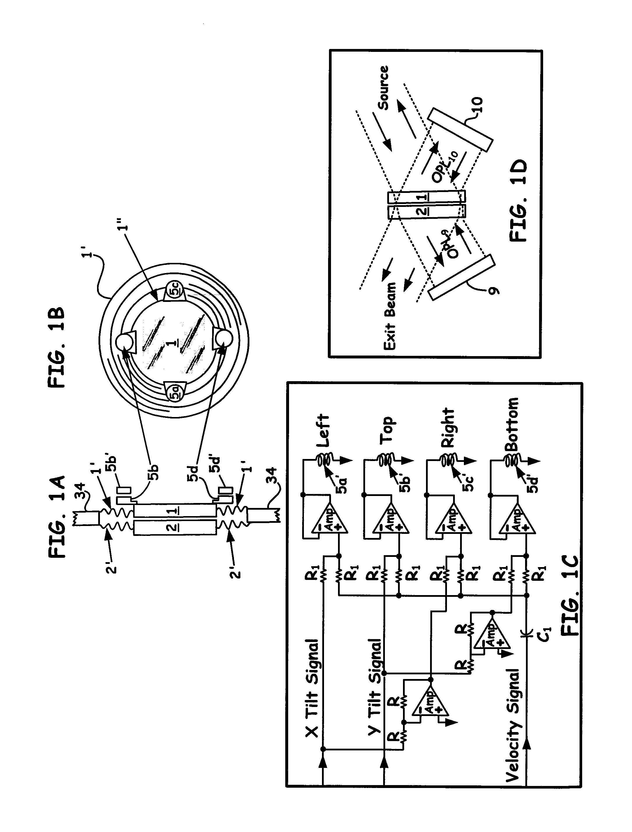
[0065]Controlling the velocity of moving beamsplitter 1 and the velocity of moving mirror assembly 27 at the same time using, for example, a standard velocity control servo (not shown) can be accomplished by allowing the inherent spring centering forces of a configured diaphragm structure (e.g., resilient flexure material 1′, as shown in FIG. 1B), to control the amount of movement of beamsplitter 1 as compared to the amount of movement with respect to mirror 9′.

[0066]As part of the configuration, a tilt control system (not shown) is integrated with system 300, as shown in FIG. 3, and the monitoring laser signals (e.g., B) are expanded, as discussed above. Operationally, beamsplitter 1 is initially resting at a center location (i.e., having zero flexure force) and a zero velocity. Moving mirror 9′ can be driven to a starting location at a configured mechanical end stop (not shown). The velocity servo is at that moment generating zero voltage and zero force.

[0067]At the mo...


PUM


Abstract

A novel means of provided velocity control of an interferometer wherein one of the moving components includes the beamsplitter element is introduced herein. Using a moving beamsplitter and coupled flexure mounting allows improved velocity control because the low mass of the beamsplitter enables the systems disclosed herein to respond faster than conventional mirror velocity controlled interferometer instruments with a resultant lower velocity error so as to provide a more stable and lower noise spectra from the analytical instrument. The control of the velocity of the beamsplitter and if desired, one or both of the configured mirrors, reduces the time wasted changing velocity at the ends of each scan. The result is an increase in data collection available in any given experiment time frame. Such desirable arrangements of the present invention thus allow scans to be collected at higher rates, which beneficially increase the ability to monitor rapidly changing systems.

Description

BACKGROUND OF THE INVENTION[0001]1. Field of the Invention[0002]The present invention relates to the field of optical scientific instrumentation. More specifically, the present invention relates to the dynamic velocity control of a moving beamsplitter and one or more of the reflective components utilized in a Fourier-Transform infrared (FTIR) interferometer.[0003]2. Discussion of the Related Art[0004]An optical interferometer used in a scientific analytical instrument relies on the interference of superimposed optical beams as part of the interrogation means. When configured as a Michelson Fourier-Transformed infrared (FTIR) instrument, the optical output of the interferometer is called an interferogram. The FTIR interferometer itself often includes a beamsplitter and two mirrors, one that is conventionally stationary, and one which is conventionally mobile. The mobile mirror moves along the optic axis while staying optically perpendicular to the light beam at all times. The movemen...

Claims


Application Information

Patent Timeline
Patent Type & Authority Applications(United States)
IPC IPC(8): G01J3/45
CPCG01J3/453
Inventor COFFIN, JOHN MAGIE
Owner THERMO ELECTRONICS SCI INSTR LLC
Why Eureka
Try Eureka