Ink-jet printing platen, and ink-jet printing device

Inactive Publication Date: 2008-07-31
BROTHER KOGYO KK
View PDF4 Cites 6 Cited by
  • Summary
  • Abstract
  • Description
  • Claims
  • Application Information

AI Technical Summary

Benefits of technology

[0039]According to the present invention droplets of the ink ejected into the grooves formed in the main body of the ink-jet printing platen are deposited on the elongate members, and the distance between the printing head and the elongate members can be adjusted, irrespective of the depth of the grooves, so as to prevent or reduce generation of an ink mist due to the ink droplets.
[0040]Further, sur

Problems solved by technology

The ink droplets deposited on the platen may cause contamination of the back surface of the following recording medium which is fed next onto the platen.
However, the reduction of the width of the V-grooves makes it difficult to form the platen, and reduces the amount of ink that can be temporarily accommodated in the V-grooves, giving rise to a risk of overflow of the ink.
On the other hand, the increase of the depth of the V-grooves results in an increase of a distance between

Method used


Image

  • Ink-jet printing platen, and ink-jet printing device
  • Ink-jet printing platen, and ink-jet printing device
  • Ink-jet printing platen, and ink-jet printing device

Examples


first embodiment

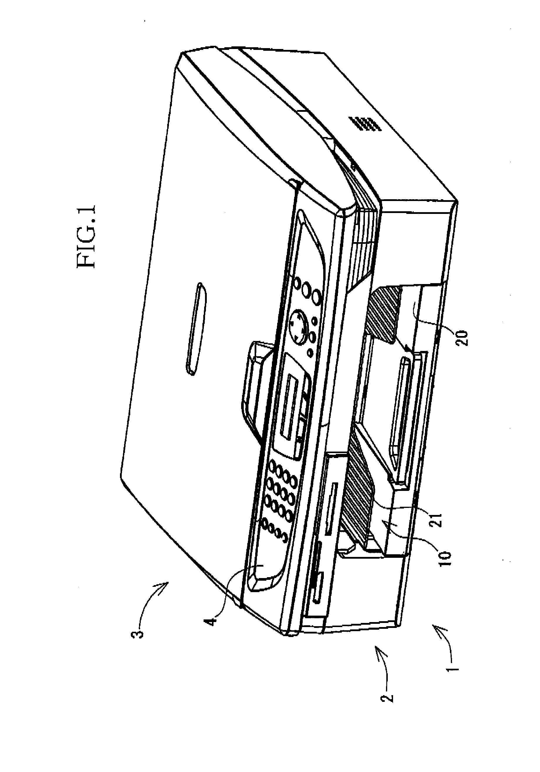
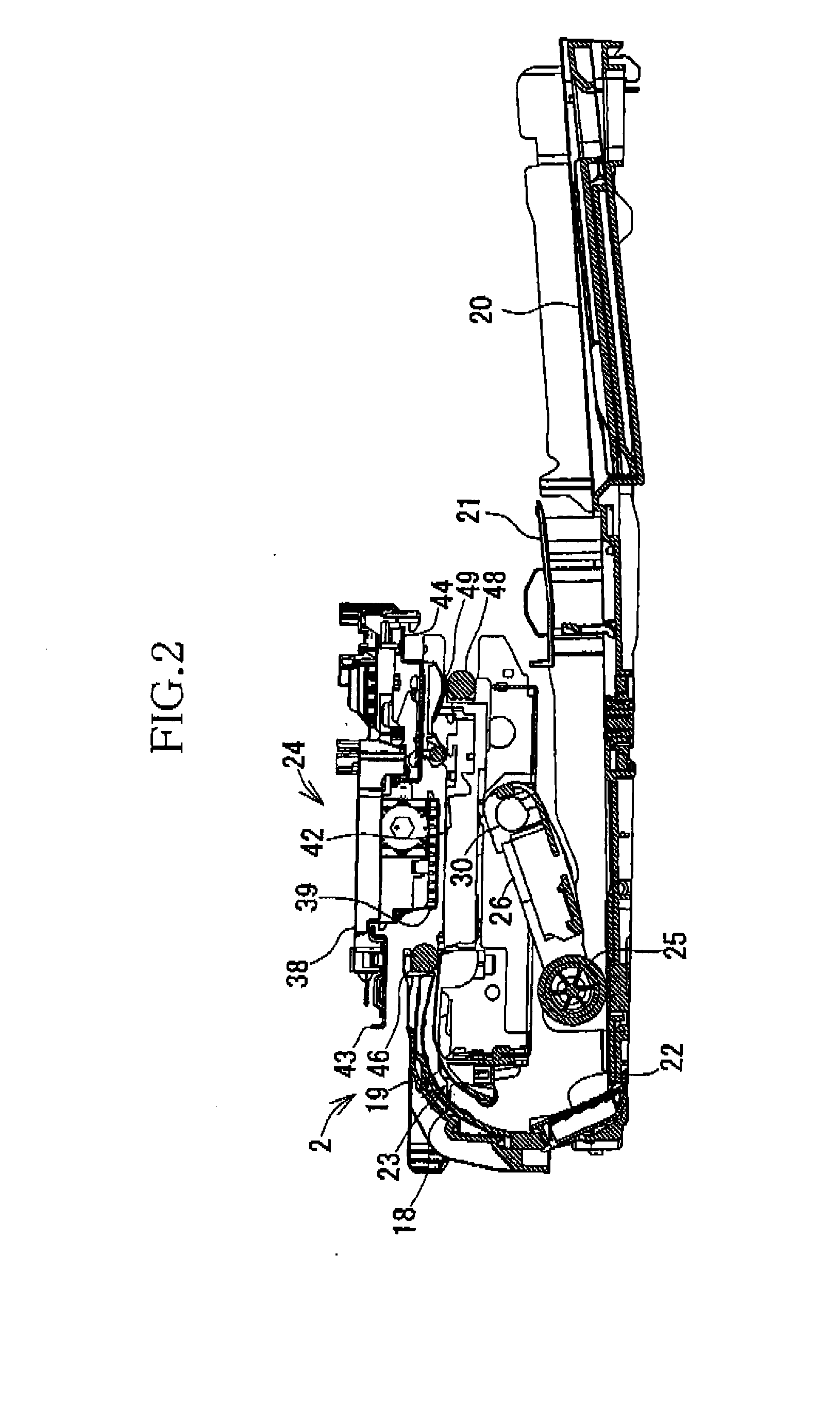
[0063]Referring first to the perspective view of FIG. 1, there is shown a multi-function device (MFD) 1 serving as an ink-jet printing device constructed according to a first embodiment of the present invention. The multi-function device 1 includes a printer portion 2 and a scanner portion 3 incorporated therein, and has a printing function, a scanning function, a copying function and facsimile transmission / reception function. The printer portion 2 and the scanner portion 3 are built in respective lower and upper parts of the multifunction device 1. The ink-jet printing device is constituted principally by the printer portion 2. Namely, the scanner portion 3, which is not a part of the ink-jet printing device of the present invention, does not directly relate to the concept of the invention, and will not be described in detail.

[0064]The printer portion 2 is configured to be operable to print an image or a text of a document on a recording medium such as a sheet of paper, according t...

second embodiment

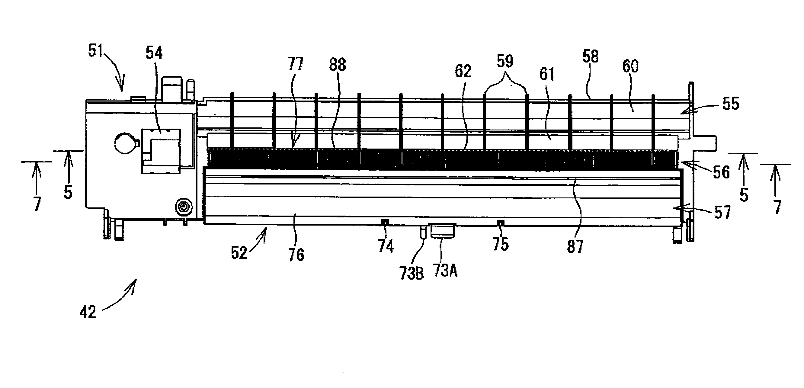
[0117]There will next be described a platen 100 constructed according to a second embodiment of this invention, which is different in construction from the platen 42 of the first embodiment. The platen 100 is used for the multi-function device 1 which includes the printer portion 2 and which is constructed as descried above with respect to the first embodiment.

[0118]FIG. 9 is a plan view of the platen 100 of the second embodiment, and FIG. 10 is a cross sectional view taken alone line 10-10 of FIG. 9, while FIG. 11 is an enlarged view of a part XI of the platen 100 of FIG. 9. FIG. 12 is a cross sectional view taken along line 12-12 of FIG. 9, and FIG. 13 is an enlarged view of a part XIII of the platen 100 indicated in FIG. 12; FIG. 14 is a cross sectional view taken along line 14-14 of FIG. 9, and FIG. 15 is an enlarged view of a part XV of the platen 100 indicated in FIG. 14;

[0119]As shown in FIG. 9, the platen 100 includes a main body 101 and a covering member 102. The ink absorb...

third embodiment

[0141]Reference is now made to the enlarged cross sectional view of FIG. 16 showing the first flow passages 91 and the second flow passage 92 partially defined by the bar-Like member 88 according to a third embodiment of this invention, which is a first modification of the first embodiment. In this modification, each bar-like member 88 has hemispherical protrusions 94, 95 which extend from its respective two opposite side surfaces and which are opposed to the respective two flank or inner side surfaces 89, 90. The hemispherical protrusions 94 are arranged at a predetermined pitch in the longitudinal direction of the bar-like member 88, that is, in the direction of extension of the groove 62. Similarly, the hemispherical protrusions 95 are arranged at the predetermined pitch in the longitudinal direction of the bar-like member 88. When the bar-like member 88 is accommodated within the groove 62, the hemispherical protrusions 94, 95 are held in contact with the respective side surface...


PUM


Abstract

An ink-jet printing platen provided in an ink-jet printing device operable to eject droplets of an ink toward a surface of a recording medium for thereby performing a printing operation on the recording medium, the ink-jet printing platen being disposed to support the recording medium in an upward direction, the ink-jet printing platen including a main body having at least one groove through which the ink can flow, and at least one elongate member each accommodated in the corresponding groove and extending along the corresponding groove, wherein the main body has an inner surface which defines the corresponding groove and cooperates with the corresponding elongate member, to define therebetween a gap extending in a longitudinal direction of the corresponding groove.

Description

CROSS REFERENCE TO RELATED APPLICATION[0001]The present application claims the priority from Japanese Patent Application No. 2007-019454 filed Jan. 30, 2007, the disclosure of which is herein incorporated by reference in its entirety.BACKGROUND OF THE INVENTION[0002]1. Field of the Invention[0003]The present invention relates in general to an ink-jet printing device, and more particularly to a platen of the ink-jet printing device.[0004]2. Description of Related Art[0005]The ink-jet printing device includes a printing head having nozzles through which droplets of an ink are selectively ejected toward a recording medium such as a sheet of paper, to print desired characters or any other images on the recording medium. The ink-jet printing device further includes an inkjet printing platen (hereinafter referred to simply as “platen”, where appropriate) which is disposed in an opposed relationship with the printing head, to support the recording medium such that the recording medium face...

Claims


Application Information

Patent Timeline
IPC IPC(8): B41J11/02
CPCB41J11/08B41J11/057
Inventor OTA, YASUHIRA
Owner BROTHER KOGYO KK
Why Eureka
Try Eureka