
Pump improvements

a technology of pump and pump body, applied in the field of pumps, can solve the problems of pump 180° out of phase, pump of this type can produce significant noise and vibration,

Inactive Publication Date: 2006-12-07
LEU SHAWN A +1
View PDF15 Cites 59 Cited by
  • Summary
  • Abstract
  • Description
  • Claims
  • Application Information

AI Technical Summary

Benefits of technology

[0011] In another aspect the pump has a flageless valve plate, meaning that the valve plate has no flange through which bolts that secure the head to the pump extend. Elimination of the flange helps cue a leak problem between the valve plate and the head that can be caused by the flanges. With the flange gone, other features may be provided on the valve plate and the head so as to angularly orient the valve plate relative to the head. Angular orientation is preferred in some applications to prevent interference with the valve or valves on the valve plate.
[0012] In another aspect, the pump has an eccentric and pistons that all have holes in them so that the pistons at opposite ends of the pump can be assembled to the shaft of the motor 180° out of phase. Two holes 180° spaced apart arc provided in one of the piston and the eccentric and one hole alignable with either of the two holes is provided in the other of the piston and the eccentric. At one end of the pump, the one hole and one of the other two holes are aligned with each other and at the other end of the pump the one hole and the other of the other two holes are aligned with each other, which results in the required 180° out of phase relative positions between the two pistons. In this aspect, a magnetic fixture can be provided with two pins to help align the three holes.

Problems solved by technology

In addition, the valve plate, which, if separate from the head, is typically provided right below the head, typically had flanges through which the rods would extend that hold the head on the housing, with the cylinder and possibly other parts in between these flanges could create problems in assembly by requiring orientation of the valve plate to register with the bolt holes of the head and also in some cases could result in leakage for example if the head flange would interfere with the range of the valve plate.
The set screw against a flat introduces errors in assembly in that they do not necessarily result in the pistons being 180° out of phase.
Also as is well known, pumps of this type can produce significant noise and vibration.

Method used


Image

  • Pump improvements
  • Pump improvements
  • Pump improvements

Examples


Embodiment Construction

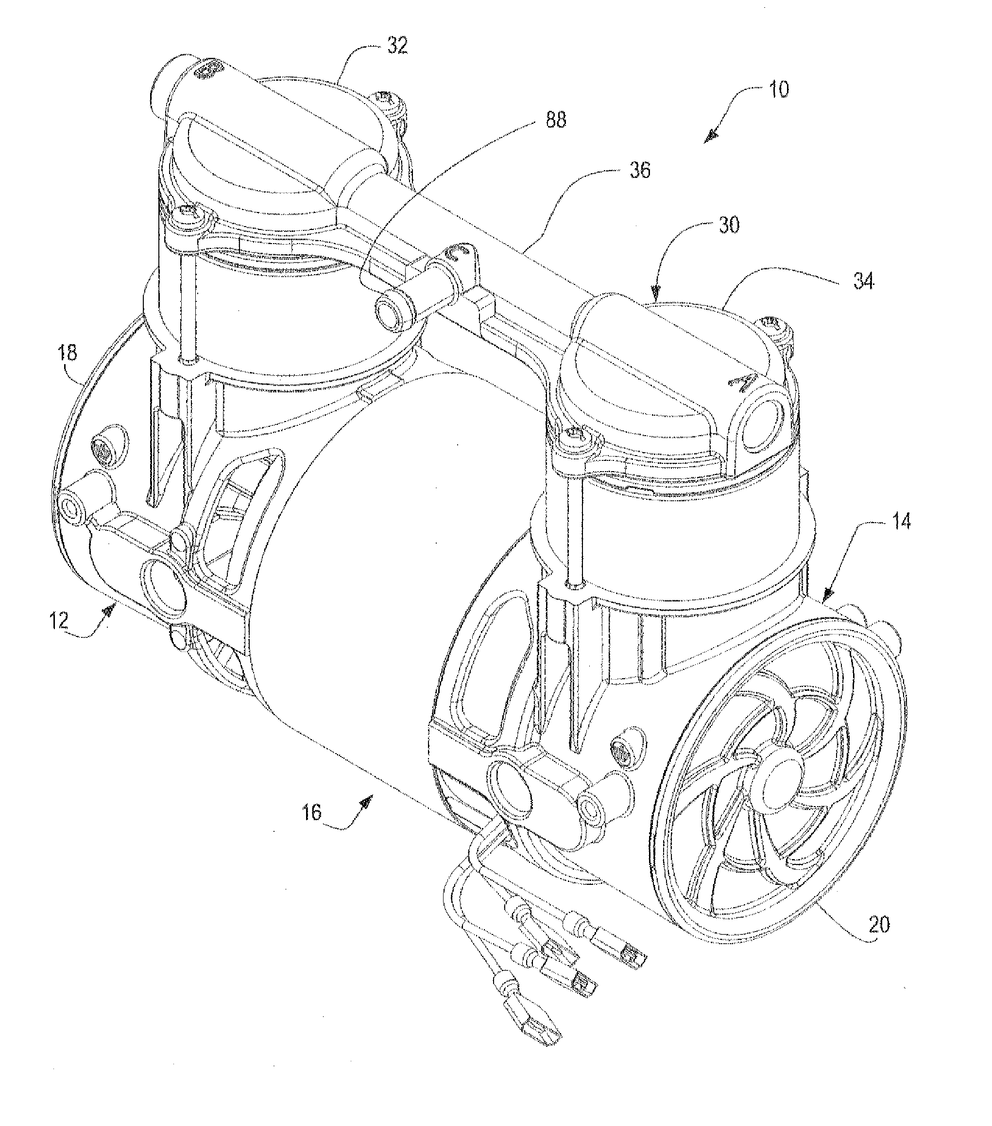
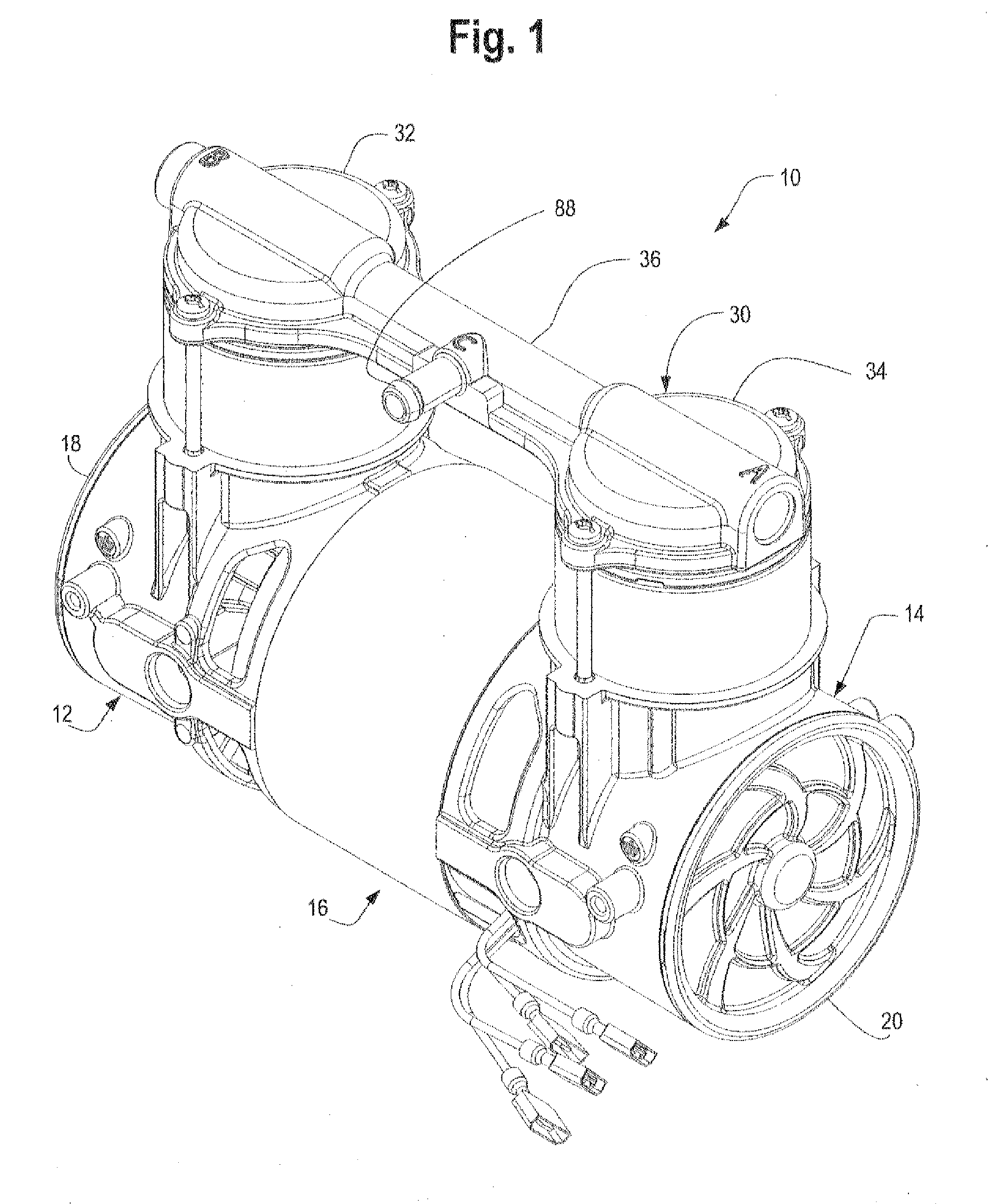
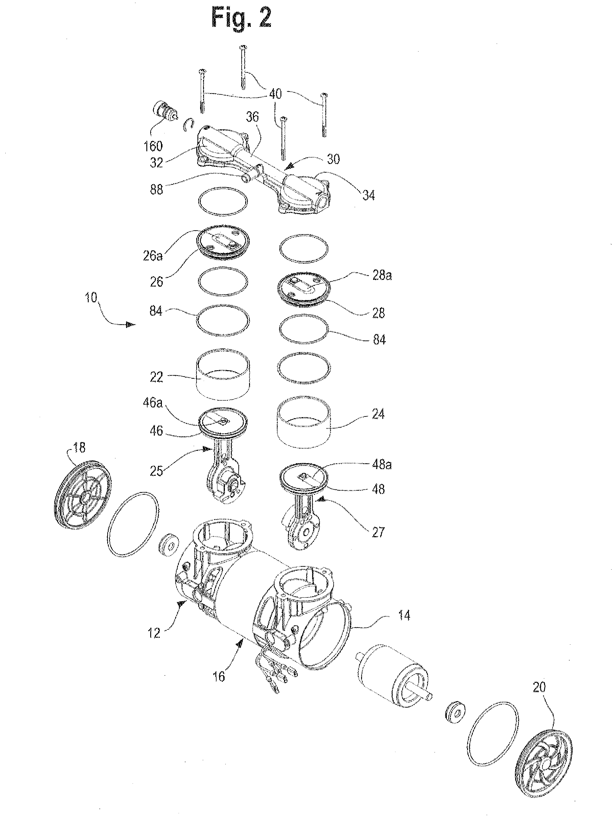
[0037] Referring to FIGS. 1-4, a pump 10 of the invention includes two housings 12 and 14 which are identical to one another, a motor 16 between the housings covers 18 and 20 on the ends of the housings opposite from the motor 16, which are also identical to one another, identical cylinders 22 and 24, identical valve plates 26 and 28, and a monolithic head 30 including two head members 32 and 34 joined integrally by a tube 36, and fasteners and seals that hold and seal all the parts together. The head 30 is bolted by bolts 40 at each end to the respective housings 12 and 14, which clamps the valve plates 26 and 28 and the cylinders 22 and 24 to the housings 12 and 14, respectively.

[0038] Referring particularly to FIGS. 4-7, the pump 10 draws its intake ail through ports 42 and 44 in the bottom of the respective housings 12 and 14. The intake flapper valves 46a, 48a to the pumping chamber are provided in the piston head 46 or 48 (FIG. 2) and through these flapper valves the air ente...


PUM


Abstract

A pump has a boltless cover that is held on the end of a housing of the pump by only a compressed ring between the cover and the housing. The pump has a flageless valve plate, meaning that the valve plate has no flange through which bolts that secure the head to the pump extend The pump has eccentrics and pistons that all have holes in them so that the pistons at opposite ends of the pump can be assembled to the shaft of the motor 180° out of phases. The pump further has a monolithic head that includes the two head members of the pump and the tube that connects them also has an integrally formed port. The pump is supported by elastomeric tubular members from its ports. The pump has a push-in fitting that can be pushed into a hole in a member such as the heads the housing or the base so that once pushed in, a ring around the fitting expands outwardly behind an edge of the body to trap the fitting in the opening.

Description

CROSS-REFERENCE TO RELATED APPLICATION [0001] This application claims priority based on its parent Provisional application No. 60 / 681,814STATEMENT CONCERNING FEDERALLY SPONSORED RESEARCH OR DEVELOPMENT [0002] Not applicable FIELD OF THE INVENTION [0003] This invention relates to pumps, both compressors and vacuum pumps, and in particular to improvements to improve the assembly and manufacture of pumps. BACKGROUND OF THE INVENTION [0004] Pumps of the general type described herein are well known. Such pumps may have one, two, or more pumping chambers and generally have a piston (e.g., a wobble piston, an articulated head piston or a diaphragm piston reciprocating in the pumping chamber that is driven by a motor. If there are two pumping chambers with parallel axes, the motor is typically between two housings that define the crankcases of the pump and join the motor to the pumping chambers, with the motor shaft axis perpendicular to the pumping chamber axis. In a useful form, a monolit...

Claims


Application Information

Patent Timeline
IPC IPC(8): F04B35/04
CPCF04B27/005F04B27/02F04B39/125F04B39/12F04B39/121F04B35/04F02B77/00F02B77/005F04B53/16F04B53/22F04B53/006F04B53/14F04B53/003F04B39/14F04B39/1066F04B37/16F05B2210/12Y10S417/00
Inventor LEU, SHAWN A.MORETTI, STEPHEN M.
Owner LEU SHAWN A
Learn More