
Exhaust Filter Module, and a Method and Apparatus for Efficiency Testing the Same

a filter module and efficiency testing technology, applied in ventilation systems, separation processes, domestic stoves or ranges, etc., can solve the problems of difficult to test a filter module in this manner, the interstitial space defined between the housing and the filter disposed therein often cannot be readily accessed by a technician, and the inability to perform downstream sampling of the installed exhaust filter

Active Publication Date: 2006-12-07
CAMFIL USA
View PDF30 Cites 22 Cited by
  • Summary
  • Abstract
  • Description
  • Claims
  • Application Information

AI Technical Summary

Problems solved by technology

However, testing a filter module in this manner is a difficult challenge.
Particularly, the interstitial space defined between the housing and the filter disposed therein often cannot be readily accessed by a technician.
Thus, downstream sampling of the installed exhaust filter often cannot be performed.
Additionally, sampling within the interstitial space defined between the housing of the module and the filter may not be accurate due to poor mixing of air within the filter housing.
This manner of testing is controversial, as many believe that some pinhole filter leaks are flow direction dependent, and as such, a filter passing an efficiency test with air flowing in a first direction, may fail when the flow through the filter is reversed to the direction used during operation of the filter of the cleanroom.
As leaking filters may pose health hazards, allow downstream contamination and present regulatory issues or other undesirable problems, it is highly desirable to test filters in the same flow direction utilized during normal filter operation.

Method used


Image

  • Exhaust Filter Module, and a Method and Apparatus for Efficiency Testing the Same
  • Exhaust Filter Module, and a Method and Apparatus for Efficiency Testing the Same
  • Exhaust Filter Module, and a Method and Apparatus for Efficiency Testing the Same

Examples


Embodiment Construction

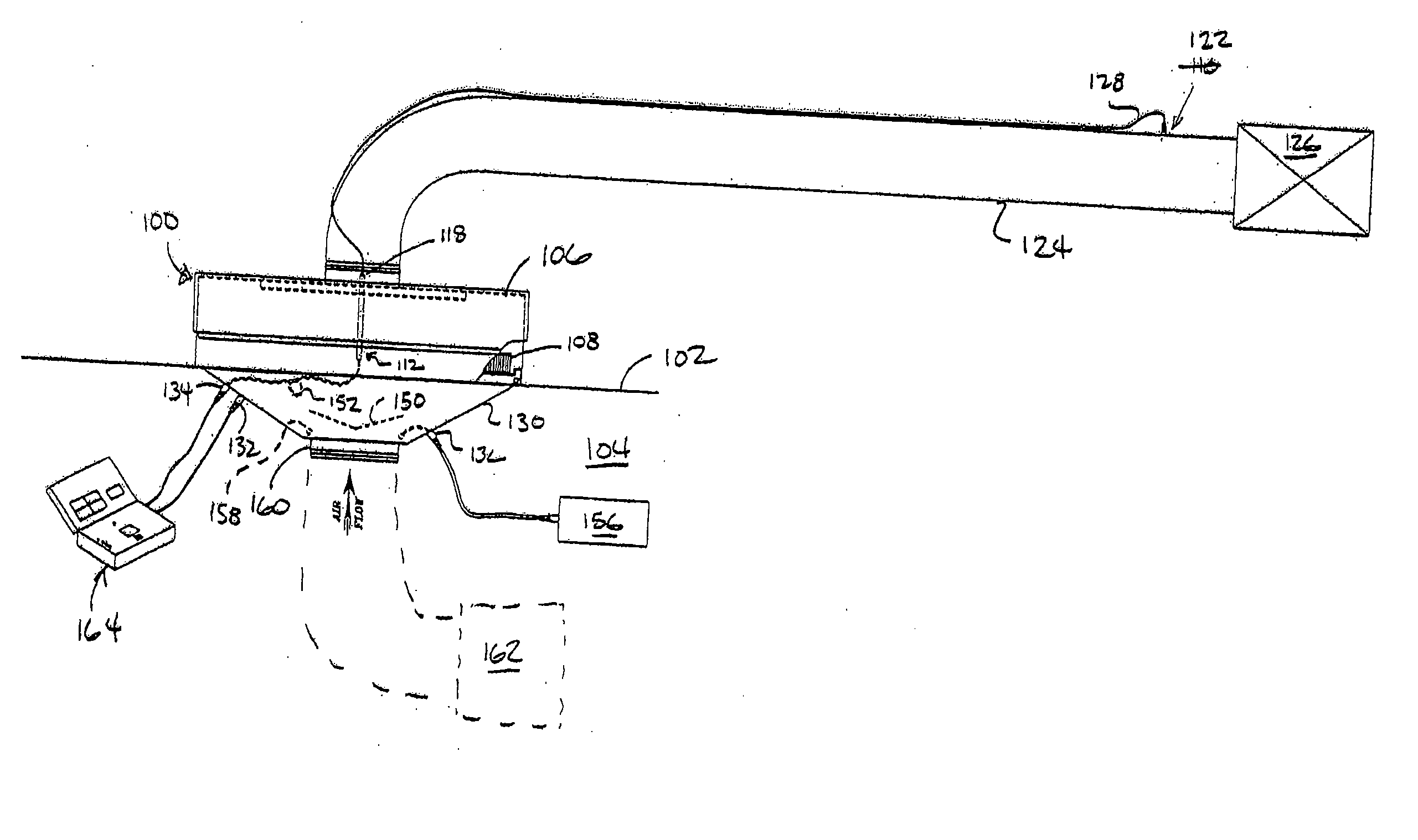
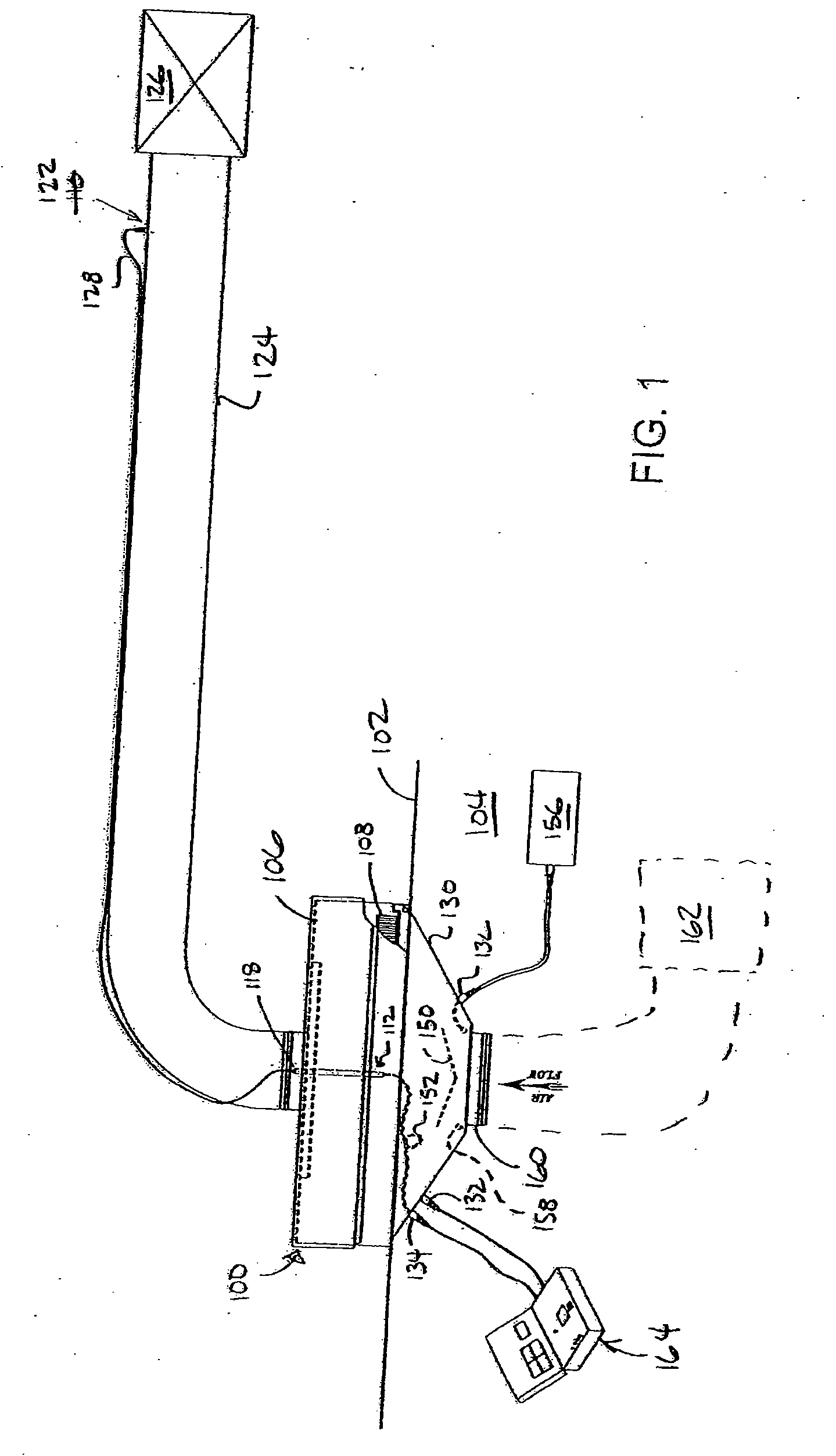
[0013] The method and apparatus for testing a filter module configured for exhaust applications is provided. The filter module itself is designed and engineered to allow for “roomside” measurement of overall filter efficiency in exhaust applications. This is not possible with conventional wall and ceiling-mounted systems because overall efficiency measurements require samples to be taken from upstream and downstream of the filter. Downstream ductwork is generally not accessible from the roomside because it is located in interstitial spaces behind hard ceilings or walls. The filter module is designed to provide the necessary connections to allow for overall efficiency measurement from the room.

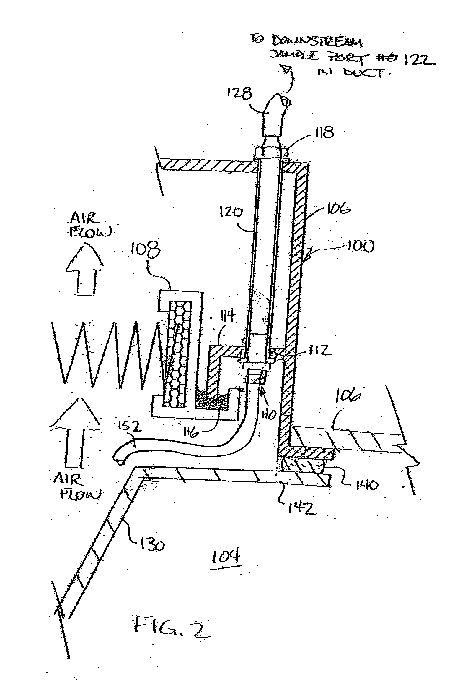
[0014]FIG. 1 depicts one embodiment of a filter module 100 configured for room exhaust applications mounting in a structure, for example, a wall, floor or ceiling 102 of a cleanroom 104. Additional partial sectional views of the filter modules 100 are depicted in FIGS. 1-3. One filter module t...


PUM

PropertyMeasurementUnit
Concentrationaaaaaaaaaa
Volumeaaaaaaaaaa
Mixtureaaaaaaaaaa

Abstract

A filter module configured for exhaust application, and a method and apparatus for testing the same are provided. In one embodiment, the filter module includes a downstream sampling port configured to allow a technician to sample flow, downstream of the filter module, from the cleanroom side of a filter module. In another embodiment, a shroud adapted to sealing engage a filter module under test is provided and includes a tube, disposed in the shroud, that couples a port to a downstream sampling port of the filter module.

Description

CROSS-REFERENCE TO RELATED APPLICATIONS [0001] This application claims benefit of U.S. Provisional Patent Application Ser. No. 60 / 663,833, filed Mar. 21, 2005, which is herein incorporated by reference in its entirety.BACKGROUND OF THE INVENTION [0002] 1. Field of the Invention [0003] Embodiments of the invention generally relate to a filter module configured for exhaust applications, and a method and apparatus for testing the same. [0004] 2. Description of the Related Art [0005] In many cleanroom and contaminant applications, filter modules are often utilized in an exhaust configuration to remove air or other fluids from rooms or equipment. In many of these applications, regulations, certifications and / or process protocols require that the filter be tested for overall efficiency after installation into the module. However, testing a filter module in this manner is a difficult challenge. Particularly, the interstitial space defined between the housing and the filter disposed therein...

Claims


Application Information

Patent Timeline
IPC IPC(8): B08B15/02F24F7/06F24F7/007B01D50/00
CPCF24F13/28F24F11/0009G01N1/22F24F2011/0093F24F11/30F24F11/39
Inventor CHERRY, SR., JOHN L.O'REILLY, SEANHUZA, MARKMORSE, THOMAS C.
Owner CAMFIL USA
Learn More