Toroidal-type continuously variable transmission

a technology of continuously variable transmission and rotating shaft, which is applied in the direction of manufacturing tools, mechanical equipment, and manufacturing tools, can solve the problems of difficult work of unified type output disk traction surfaces, inability to ground traction surfaces with high precision, and inability to achieve high precision, enhance power transmission efficiency of output disks, and prevent gear change operations.

Inactive Publication Date: 2006-12-07
NSK LTD
View PDF7 Cites 96 Cited by
  • Summary
  • Abstract
  • Description
  • Claims
  • Application Information

AI Technical Summary

Benefits of technology

[0008] The present invention aims at eliminating the above-mentioned drawbacks found in the conventional toroidal-type continuously variable transmission. Accordingly, it is an object of the invention to provide a toroidal-type continuously variable transmi...

Problems solved by technology

However, the unified type output disk cannot be processed with high precision and, especially, the traction surfaces of the unified type output disk are difficult to work.
However, in the case of the unified type output disk disclosed in either of the above-cited JP-A-2000-104804 or U.S. Pat. No. 5,607,372, the plane of the near-to-inside diameter portion of the unified type output disk must be used as the machining datum surface; and, theref...

Method used


Image

  • Toroidal-type continuously variable transmission
  • Toroidal-type continuously variable transmission
  • Toroidal-type continuously variable transmission

Examples


second embodiment

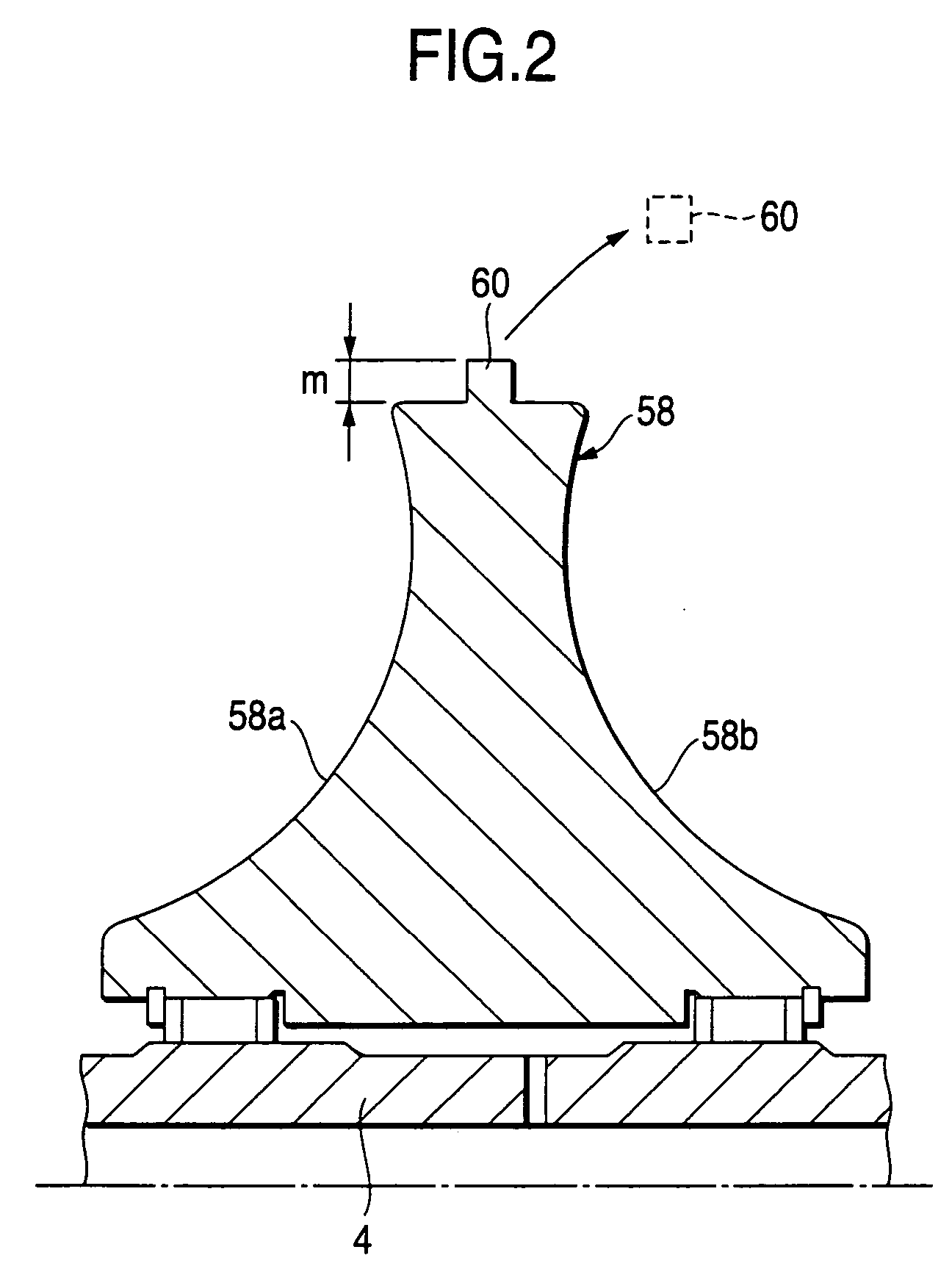
[0029] Next, FIG. 2 is a half section view of a unified type output disk 58 according to the invention.

[0030] The unified type output disk 58 according to the second embodiment includes traction surfaces 58a, 58b on the two side portions thereof (by the way, although not shown, on the portion of the disk 58 that is situated lower than the main shaft 4 as well, there are formed other two traction surfaces). In the end portion of the outer-most outside diameter portion of the present unified type output disk, there is formed a stepped portion 60 which serves as a machining datum when working the traction surfaces 58a, 58b. The length m of the stepped portion 60 in the diameter direction thereof (that is, the direction which intersect at right angles to the axis of the main shaft 4) is set at least 2 mm or more.

[0031] Also, an operation for finishing the stepped portion 60 is carried out after enforcement of the heat treatment of the unified type output disk 58.

[0032] And, referring ...

third embodiment

[0037] Next, FIG. 3 is a half section view of a unified output disk 62 according to the invention.

[0038] The unified type output disk 62 according to the third embodiment includes traction surfaces 62a, 62b on the two side portions thereof (by the way, although not shown, on the portion of the disk 62 that is situated lower than the main shaft 4 as well, there are formed other two traction surfaces). In the end portion of the outer-most outside diameter portion of the present unified type output disk, there is formed a groove portion 64 which serves as a machining datum when working the traction surfaces 62a, 62b. The length m of the wall surface of the groove portion 64 in the diameter direction thereof (that is, the direction which intersect at right angles to the axis of the main shaft 4) is set at least 2 mm or more.

[0039] Also, the operation for finishing the groove portion 64 is carried out after enforcement of the heat treatment of the unified type output disk 62.

[0040] And...


PUM

PropertyMeasurementUnit
Diameteraaaaaaaaaa

Abstract

A toroidal-type continuously variable transmission, has a first continuously variable transmission mechanism and a second continuously variable transmission mechanism: wherein the first and second continuously variable transmission mechanisms are disposed coaxially with each other; the first and second input disks are connected together so as to be rotated in synchronization with each other; the first and second output disks are formed as a unified type output disk including traction surfaces on the two side surfaces thereof; on the side portion at the outer-most outside diameter of the unified type output disk, there is formed a datum plane serving as a machining datum when the traction surfaces are processed; and, an operation for finishing the datum plane is carried out after the unified type output disk is heat treated.

Description

BACKGROUND OF THE INVENTION [0001] 1. Field of the Invention [0002] The present invention relates to a toroidal-type continuously variable transmission. [0003] 2. Description of the Related Art [0004] Conventionally, as a toroidal-type continuously variable transmission, there is known an apparatus structured such that first and second continuously variable transmission mechanisms are disposed coaxially with each other: specifically, the first continuously variable transmission mechanism comprises a first input disk, a first output disk disposed so as to be opposed to the first input disk and a pair of power rollers respectively held between the first input and output disks; the second continuously variable transmission mechanism comprises a second input disk, a second output disk disposed so as to be opposed to the second input disk and a pair of power rollers respectively held between the second input and output disks; the first and second continuously variable transmission mechan...

Claims


Application Information

Patent Timeline
IPC IPC(8): F16H15/38
CPCF16H15/38Y10T29/4981F16H2015/383
Inventor IMANISHI, TAKASHI
Owner NSK LTD
Why Eureka
Try Eureka