Fastener for securing a cargo container

Active Publication Date: 2006-12-14
HSIEH DAVID
View PDF2 Cites 10 Cited by
  • Summary
  • Abstract
  • Description
  • Claims
  • Application Information

AI Technical Summary

Benefits of technology

[0006] Therefore, the object of the present invention is to provide a fastener that has a larger contact area betw

Problems solved by technology

However, since the engagement element is spherical in shape, the contact area between the engagement element and t

Method used


Image

  • Fastener for securing a cargo container
  • Fastener for securing a cargo container
  • Fastener for securing a cargo container

Examples


Embodiment Construction

[0014] The construction of a preferred embodiment of the fastener according to the present invention will now be described in greater detail below.

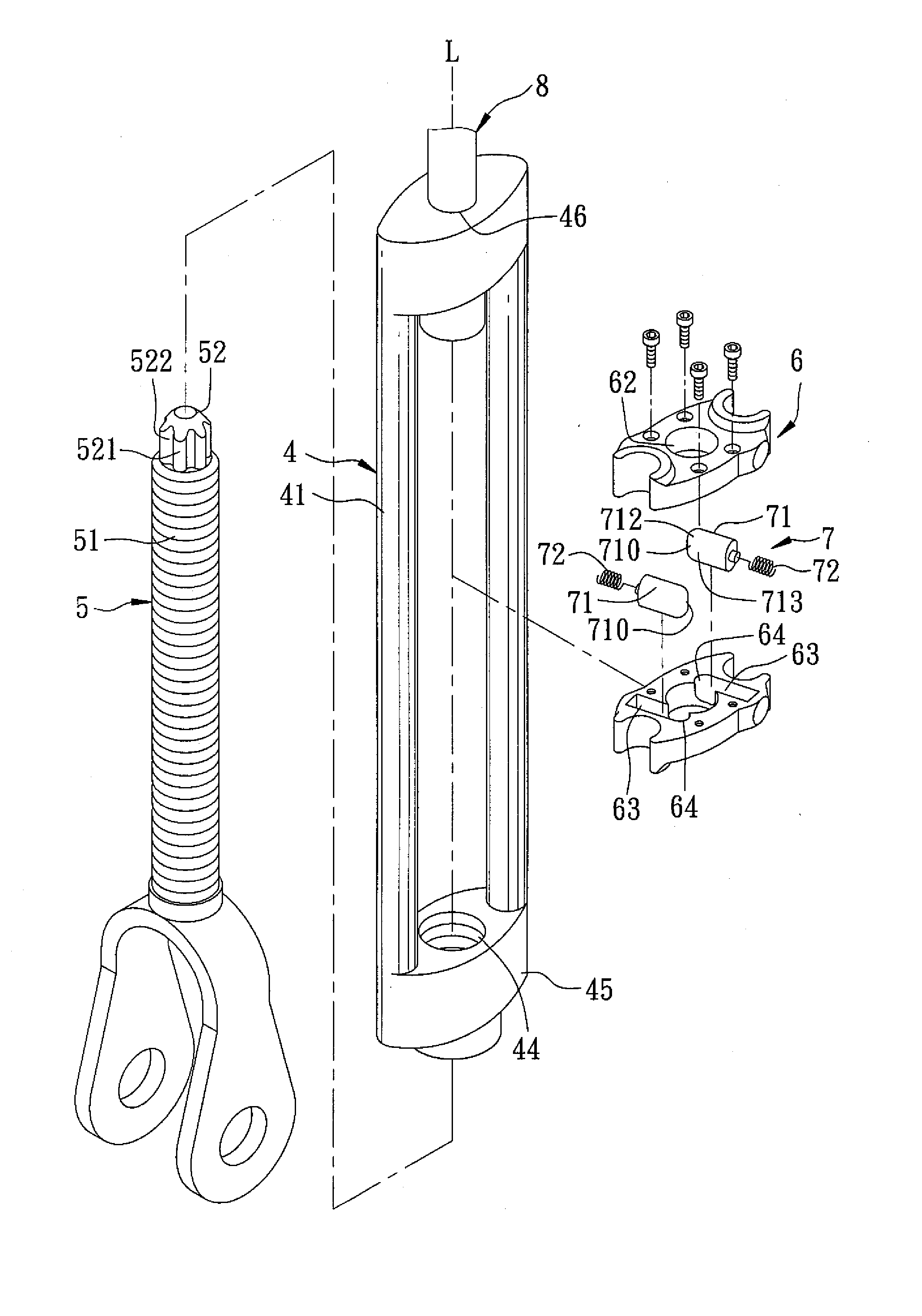
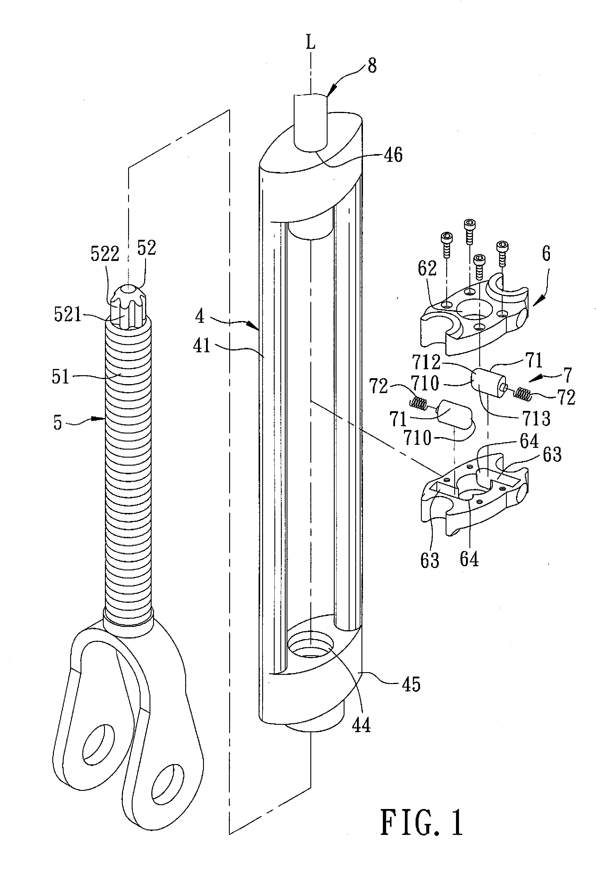
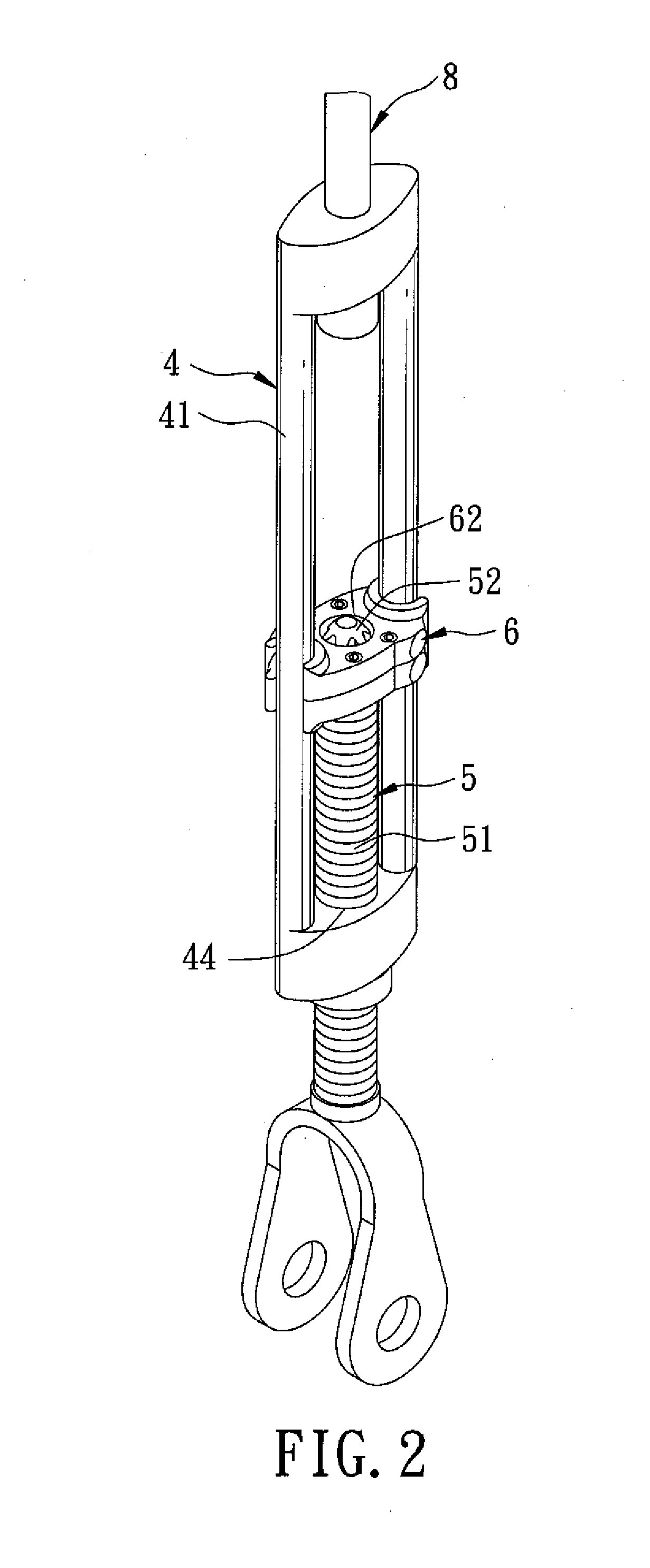
[0015] With reference to FIGS. 1 to 3, a fastener for securing a cargo container according to a preferred embodiment of the present invention includes: a first fastener component 4 including first and second fixed bodies 45, 46, and a pair of rails 41 bridging the first and second fixed bodies 45, 46, the first fixed body 45 having a screw hole 44; amounting seat 6 mounted slidably on the rails 41 for sliding along the rails 41 and having a central through-hole 62 aligned with the screw hole 44 in an axial direction (L), and a pair of opposite retaining recesses 63 in spatial communication with and extending in tangential directions (T1, T2) from the central through-hole 62; a second fastener component 5 including a threaded shaft 51 extending threadedly through the screw hole 44 in the first fixed body 45 toward the second fixed body 46...


PUM


Abstract

A fastener for securing a cargo container includes: a first fastener component including a pair of rails; amounting seat mounted slidably on the rails; a second fastener component including a toothed part extending into the a central through-hole in the mounting seat and formed with teeth, each of which has a contact surface; and an engagement unit including an engaging element that is mounted in a retaining recess in the mounting seat and that has a free end portion extendable into the central through-hole in the mounting seat. The free end portion of the engaging element has a flat contact surface that extends into the central through-hole to abut against the contact surface of an adjacent one of the teeth in such a manner to arrest rotation of the mounting seat relative to the second fastener component in a direction.

Description

CROSS-REFERENCE TO RELATED APPLICATION [0001] This application is a continuation-in-part (CIP) of U.S. patent application Ser. No. 11 / 062,070, filed by the applicant on Feb. 18, 2005, and claims the priority of Taiwanese Application No. 094215678, filed on Sep. 12, 2005.BACKGROUND OF THE INVENTION [0002] 1. Field of the Invention [0003] The present invention relates to a fastener for a cargo container, more particularly to a fastener having a non-spherical shaped engaging element and a threaded shaft with a toothed part for engaging the engaging element. [0004] 2. Description of the Related Art [0005] In co-pending U.S. Patent Application Ser. No. 11 / 062,070, the applicant disclosed a fastener that includes a mounting seat slidable on a pair of rails and formed with a central hole and a retaining recess, a threaded shaft extending threadedly through a fixed body interconnecting the rails, a toothed part extending from the threaded shaft into the central hole, and a spring-biased sph...

Claims


Application Information

Patent Timeline
IPC IPC(8): B63B25/00B63J99/00
CPCF16B7/06F16B35/044F16B33/002
Inventor HSIEH, DAVID
Owner HSIEH DAVID
Why Eureka
Try Eureka