Infinity tunnel display system with floating dynamic image

a dynamic image and display system technology, applied in the field of optical display systems, to achieve the effect of less maintenance, no heat, and longer li

Inactive Publication Date: 2006-12-21
ROBINSON DOUGLAS L +2
View PDF14 Cites 43 Cited by
  • Summary
  • Abstract
  • Description
  • Claims
  • Application Information

AI Technical Summary

Benefits of technology

[0013] An advantage of the present invention is that it provides a moving image within the infinity tunnel and creates the illusion of a floating three-dimensional image. Additionally, prior art infinity tunnel systems typically incorporate incandescent light bulbs mounted in front of the mirror from the sides of the enclosure. The present invention incorporates LEDs that preferably protrude through the mirror. The LEDs typically have a life of approximately eleven years, as opposed to less than one year for incandescent lights. LEDs produce no heat, and the light of a LED is focused in a cone pattern toward the beamsplitter, rather than in all directions, as in the case of an incandescent bulb. The result is less stray light inside the system, a brighter, crisper light image pattern, less maintenance, with no heat, and longer life.

Problems solved by technology

In addition, recessed lighting fixtures may be employed to illuminate the interior area of the device in a manner whereby the lighting fixtures are not readily viewable from a location exterior to the device

Method used


Image

  • Infinity tunnel display system with floating dynamic image
  • Infinity tunnel display system with floating dynamic image
  • Infinity tunnel display system with floating dynamic image

Examples


Embodiment Construction

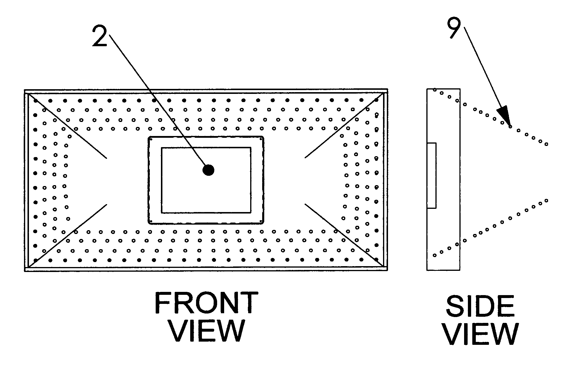
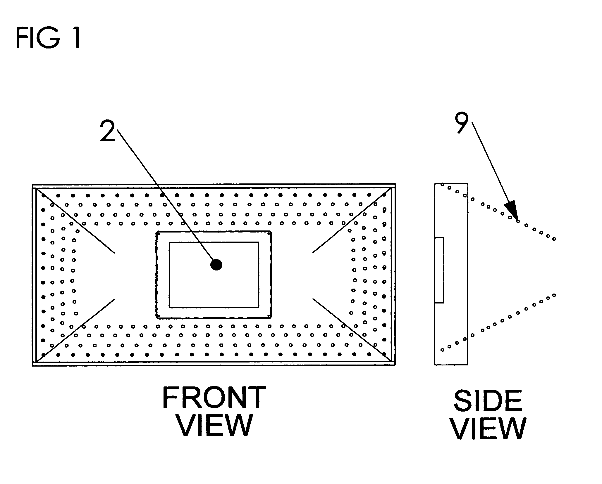
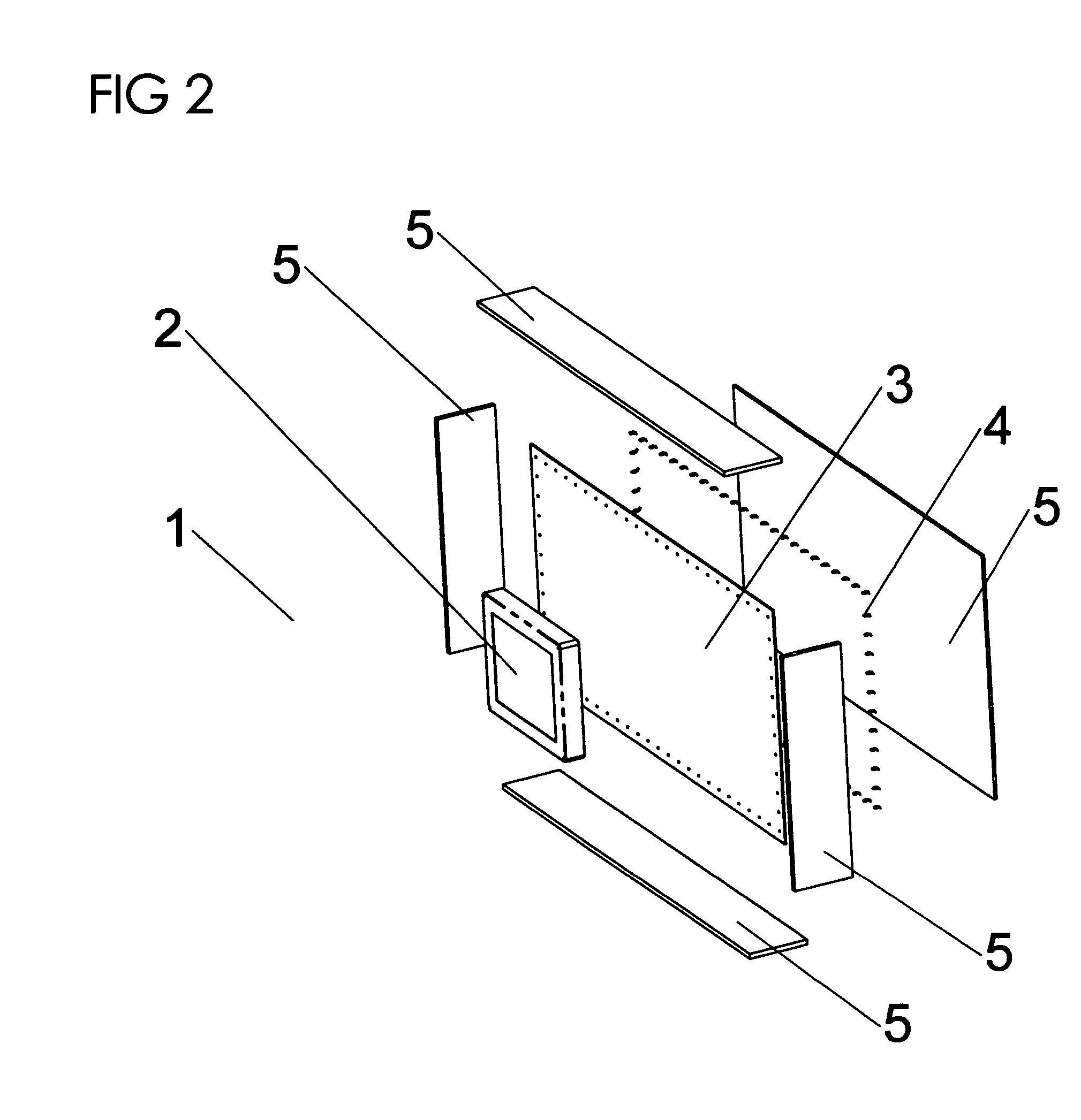
[0021] The present invention provides methods and apparatus for creating an illusion, in an optical display actually having a relatively shallow depth, of a tunnel having infinite depth a moving image floating in the center of the tunnel.

[0022] In a preferred embodiment, device incorporates a mirror and beamsplitter and a series of LEDs to create multiple images of the series of LEDs, which seem to appear in an infinite number of layers extending back into the display. The system further incorporates a LCD mounted between the front beamsplitter and the rear reflective mirror. The partially reflective front beamsplitter preferably hides the frame or housing of the LCD panel, making it nearly invisible from the front viewing position. The image produced on the LCD screen is visible through the beamsplitter, from the front of the device. In one embodiment, the image on the LCD shows bright colorful moving objects, rendered with shading to create the visual cue of a three-dimensional o...


PUM


Abstract

An optical display apparatus includes a housing, a partially reflective front window or beamsplitter having a front side forming a face of the housing, wherein the front window or beamsplitter appears transparent from the face of the housing and is at least partially reflective to light coming from within said housing, a mirror of glass, plastic, stretched mirror-coated thermoplastic film or other reflective substrate, located within the housing and positioned at a predetermined distance behind the front window or beamsplitter, a plurality of LEDs arranged proximate to the mirror, such that light is transmitted from the mirror to a rear side of the front window or beamsplitter, a LCD monitor or CRT or other display device or screen positioned and near coincident to the rear side of the front window or beamsplitter, and a circuit for controlling the LEDs.

Description

BACKGROUND OF THE INVENTION [0001] 1. Field of the Invention [0002] The invention pertains to the field of optical display systems. More particularly, the invention pertains to methods and apparatus for creating an illusion, in an optical display actually having a relatively shallow depth, of a tunnel having infinite depth with a moving image floating in the center of the tunnel. [0003] 2. Description of Related Art [0004] The so-called “infinity tunnel” is a device based on simple principles of optics, generally comprising a series of reflectors and lights, which are arranged to create the illusion of a never-ending tunnel of lights. The infinity tunnel was developed as a novelty item in the 1930s and was later embraced by the popular culture of the 1970s, coincident with the availability of semi-reflective architectural glass, which functions as a partially mirrored window or beamsplitter. The infinity tunnel typically was incorporated into clocks, wall mirrors and novelty gifts, ...

Claims


Application Information

Patent Timeline
Patent Type & Authority Applications(United States)
IPC IPC(8): G09G5/00
CPCG09F19/12
Inventor ROBINSON, DOUGLAS L.WESTORT, KENNETH S.TURNER, RANDOLPH J.
Owner ROBINSON DOUGLAS L
Why Eureka
Try Eureka