
Method for printing corrugated sheet

a corrugated sheet and printing method technology, applied in printing, typewriters, other printing apparatuses, etc., can solve the problems of impaired dots retention on the sheet, and achieve the effect of preventing warping and shifting of the sh

Inactive Publication Date: 2006-12-21
ISOWA IND CO LTD
View PDF5 Cites 23 Cited by
  • Summary
  • Abstract
  • Description
  • Claims
  • Application Information

AI Technical Summary

Benefits of technology

[0027] In one embodiment of the printing method according to the present invention, when the cardboard sheets with corrugated surfaces are transferred toward the ink jet nozzles one by one, warping and shifting of the sheets can be prevented by sucking one of two surfaces of each of the sheets with a certain suction force. When each of the sheets crosses the ink jet nozzles, ink droplets each having a predetermined volume are jetted toward the corrugated surface, that is, the other of the two surfaces, and land on the sheet, and then dots are formed on the sheet, whereby the print image is created on the corrugated surface.
[0029] By adjusting the relationship among the transferring velocity of the sheet, the suction force of the sheet, and the distance between the tip of each of the ink jet nozzles and the corrugated surface in accordance with the configuration of the corrugated surface including the height of the flute, the wavelength of the corrugation, etc. and DPI (dot per inch) of dots, when the cardboard sheets are printed by the ink jet type printing, even though the suction force can influence the ink droplets jetted from the tip of each of the ink jet nozzles toward the corrugated surface via the gaps between adjacent sheets in the transferring direction, the print image can be prevented from being faded by securing the retention of dots on the corrugated surface while at the same time by limiting the overlapping of dots within an acceptable range, and as a result, a clear print image with an-esthetic appearance at desired positions on the corrugated surface can be obtained.
[0030] More specifically, as to the relationship between the suction strength of the sheet and the distance between the tip of each of the ink jet nozzles and the corrugated surface, the less the distance becomes, the greater the efficiency of the printing becomes. On the other hand, the bigger the suction strength becomes, the more important it is that warping of the sheet be prevented. In addition, the retention of dots on the sheet can be impaired due to the high permeability of the cardboard, if the value of the suction force exceeds a certain value, whereby the printing image becomes fade, whereas the greater the distance between the tip of each of the ink jet nozzles and the corrugated surface becomes, although the jamming up of the sheet due to the warp of the sheet can be avoided even under a small suction force, the more the deviation of the ink droplets on the sheet from the desired positions becomes due to the fact that a flight path of each of the ink droplets between the ink jet nozzles and the corrugated surface becomes long accordingly.

Problems solved by technology

In addition, the retention of dots on the sheet can be impaired due to the high permeability of the cardboard, if the value of the suction force exceeds a certain value, whereby the printing image becomes fade, whereas the greater the distance between the tip of each of the ink jet nozzles and the corrugated surface becomes, although the jamming up of the sheet due to the warp of the sheet can be avoided even under a small suction force, the more the deviation of the ink droplets on the sheet from the desired positions becomes due to the fact that a flight path of each of the ink droplets between the ink jet nozzles and the corrugated surface becomes long accordingly.

Method used


Image

  • Method for printing corrugated sheet
  • Method for printing corrugated sheet
  • Method for printing corrugated sheet

Examples


Embodiment Construction

[0045] A printing method of one embodiment of the present invention will be described below by which is an image is printed on a so-called core liner having a meandering corrugation.

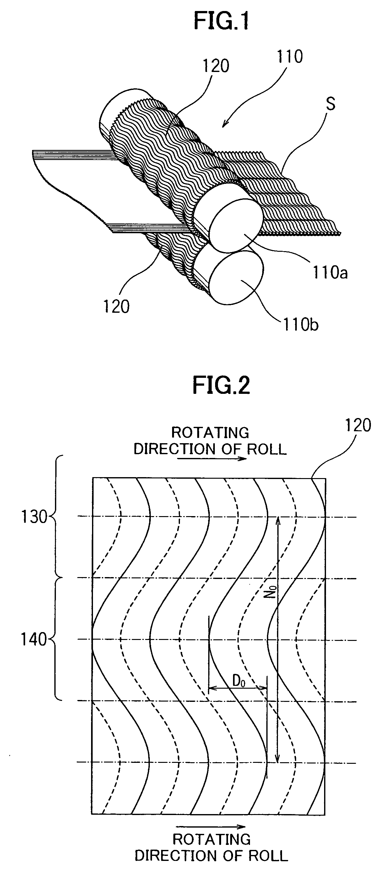
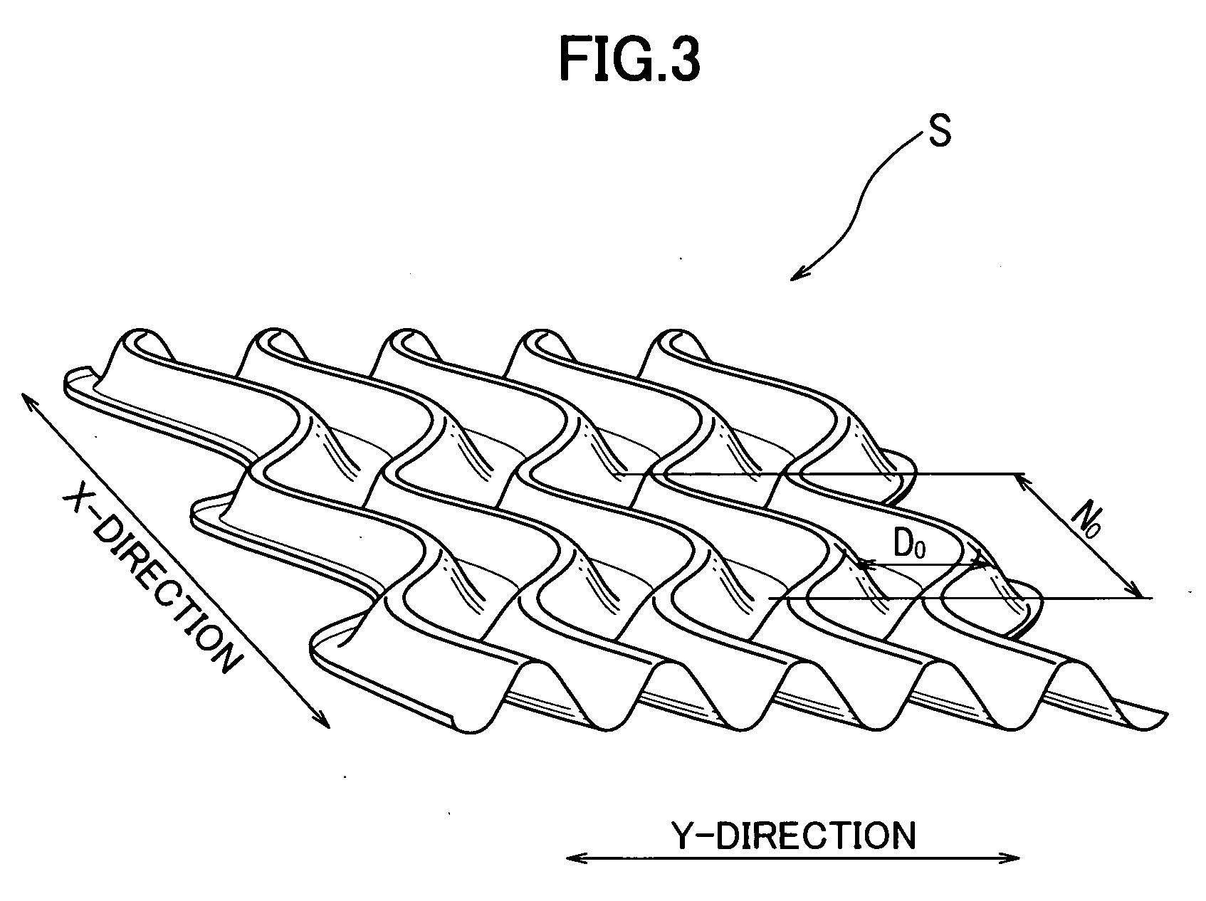
[0046] As can be seen in FIG. 1, an apparatus for manufacturing the meandering corrugated sheet includes a pair of rollers having an upper roller 110a and a lower roller 110b, and when a flat sheet is transferred between the rollers under a predetermined nip pressure, a sheet having waves extending in a width (X) direction as well as a feeding (Y) direction is formed, as shown in FIG. 3. The degree of the meandering, that is, the wave in the width (X) direction, is typically indicated by D0 / N0 in FIG. 2.

[0047] More particularly, each of the rollers have a number of teeth 120 formed on the outer surface thereof. FIG. 2 shows an expansion plan view of the teeth 120. As can be seen in FIG. 2, the teeth 120 include front teeth 130 for forming a front wave portion of the sheet located in advance with respec...


PUM


Abstract

A method for printing corrugated cardboard sheets is effected by transferring the corrugated cardboard sheets while jetting ink droplets from ink jet nozzles onto the corrugated cardboard sheets to form dots thereon. Said method comprises the steps of transferring the corrugated cardboard sheets one by one while at the same time sucking one flat surface of each of the corrugated cardboard sheets, and adjusting the relationship among the velocity at which the corrugated cardboard sheets are transferred, the suction force of the corrugated cardboard sheets, and the distance between the ink jet nozzle and the other corrugated surface of each of the corrugated cardboard sheets in accordance with the configuration of the said other corrugated surface and the desired DPI of dots to be formed on the said other corrugated surface. As a result, the ink droplets are jetted toward the said other corrugated surface to be printed thereon.

Description

FIELD OF THE INVENTION [0001] The present invention relates to a printing method for ink-jet type printing. More particularly, the present invention relates to a method for printing a clear image on cardboard sheets having a corrugated surface. BACKGROUND OF THE INVENTION [0002] As disclosed in Japanese Patent Laid-open Publication HEI10-286939A, a printing machine for printing an endless sheet by jetting ink from a fixed ink jet nozzles toward the sheet in a ink jet type has been conventionally used. [0003] This printing machine comprises a transferring device for transferring an endless sheet, ink jet nozzles disposed at a side of the sheet to be printed to be spaced apart from the surface to be printed. The ink jet nozzles are disposed to be a predetermined distance between the tip of the ink nozzle and the surface to be printed. [0004] According to this printing machine, by transferring the endless sheet by the transferring device, the printing is carried out by the ink droplets...

Claims


Application Information

Patent Timeline
IPC IPC(8): B41J2/01
CPCB41J11/0085B41J3/407
Inventor HATASA, KAZUHIROKATO, SYUNJIYAMAZAKI, HIROSHIIHARA, SHUNICHI
Owner ISOWA IND CO LTD
Learn More