Date display assembly for an electronic device

a technology of electronic devices and date display, applied in the direction of electromechanical clocks, instruments, electric indications, etc., can solve the problems of less efficiency, slower tens digit change rate, perceived deficiencies of constructions, etc., to achieve efficient and reliable date display methods, reduce energy and rotation time, and reduce construction costs

Inactive Publication Date: 2006-12-21
TIMEX GROUP
View PDF8 Cites 10 Cited by
  • Summary
  • Abstract
  • Description
  • Claims
  • Application Information

AI Technical Summary

Benefits of technology

[0005] It is thus an objective of the present invention to provide an improved date display assembly that requires less rotation of the tens disc, thus minimizing the energy and rotation time needed, thereby simultaneously providing a more efficient and reliable date display methodology.
[0006] It is still another objective of the present invention to provide an improved date display assembly that provides for a cleaner and quicker rotation of the tens disc than achieved by the prior art constructions.

Problems solved by technology

However, such constructions have perceived deficiencies.
For example, it is believed that the construction set forth in the aforementioned published application requires an excessive amount of rotation of the tens disc (450°) when the date moves from “09” to “10,”“19” to “20” and “29” to “30.” Accordingly, it is believed that the rate at which the tens digit changes is slower than desirable and performed with less efficiency.

Method used


Image

  • Date display assembly for an electronic device
  • Date display assembly for an electronic device
  • Date display assembly for an electronic device

Examples


Embodiment Construction

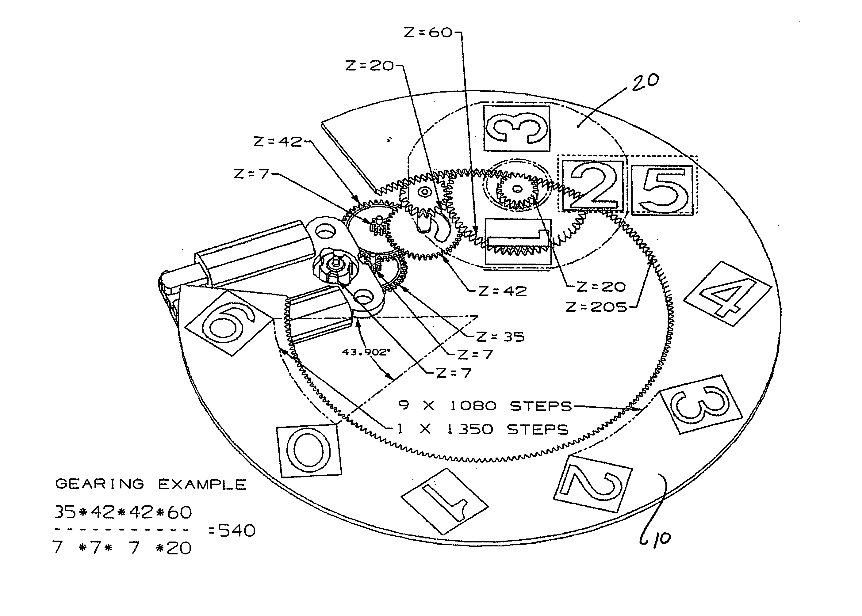
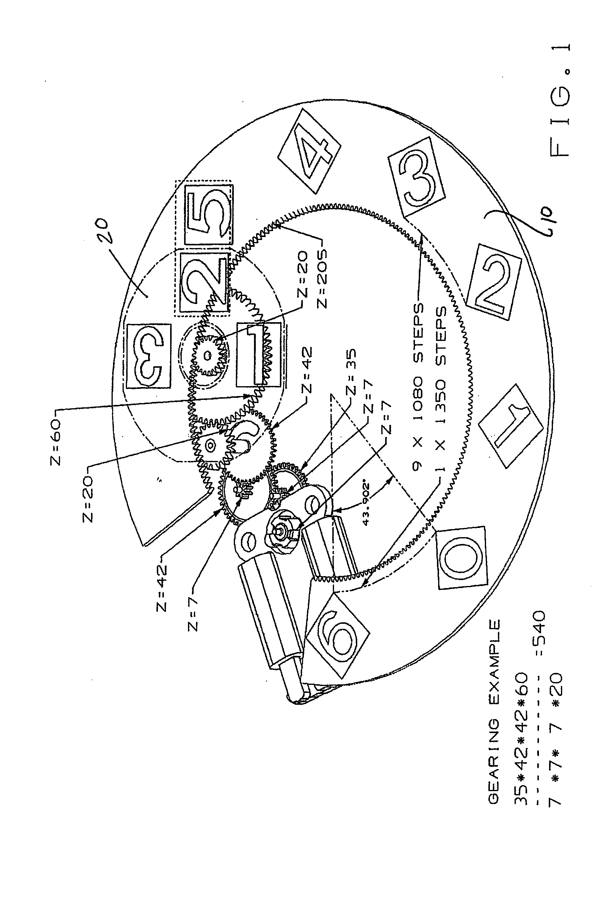
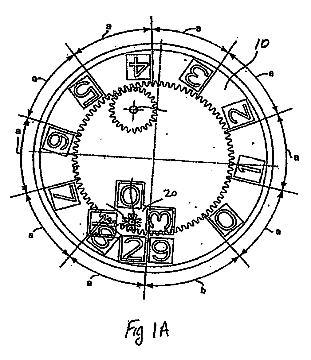
[0013] Reference is first made to FIGS. 1 and 1A which illustrate a date display assembly employing the construction set forth in U.S. application Ser. No. 10 / 407,169. As set forth in the '169 application, each time the units ring is moved by the angular value corresponding to the distance between digits (e.g. 0 to 1, 1 to 2, . . . 8 to 9 (and excepting 9 to 0)) the tens disc carries out a full rotation (i.e. 360°), and when the units ring is moved through an angular value corresponding to the sector between the 9 and 0 digits, the tens disc carries out a whole number turn plus a quarter turn (e.g. 450°). It is clear from FIGS. 1 and 1A that the rotational directions of the units ring and the tens disc are the same. Thus, during passage of the units numerals 0 to 1, 1 to 2 . . . 7 to 8 and 8 to 9 in the clockwise direction, the tens disc carries out one complete revolution (i.e. rotating 360° in the clockwise direction) and the numeral indicating the tenth remains the same. By contr...


PUM


Abstract

A date display assembly for displaying the day of the month in an electronic device, the assembly comprising a units ring and a tens disc, the units ring comprising at least one series of numerals from 0 to 9 and the tens disc comprising a series of numerals from at least 1 to 3 and optionally the numeral 0; wherein the units ring and the tens disc being positioned relative to each other so as to display in the space of a window two numerals side by side, one of which is carried by the units ring and the other of which is carried by the tens disc, wherein the units ring is divided into ten sectors or a multiple of ten sectors each separating the numerals 0 to 9, the one sector separating the numerals 9-0 having an angular extent equal to ¾ of the angular extent of the sectors separating the other numerals. In the preferred embodiment, the device is a timepiece and a wristwatch in particular.

Description

RELATED APPLICATIONS [0001] This application claims the benefit of U.S. Provisional Application Nos. 60 / 691,914, filed Jun. 17, 2005 and 60 / 754,854 filed Dec. 29, 2005.BACKGROUND OF THE INVENTION [0002] The present invention relates to a date display assembly for displaying the day of the month, particularly for a timepiece of the type comprising a two-ring / disc (units, tens) assembly. Such an assembly, among other things, facilitates the use of large digits on the rings or discs, thereby providing, among other things, a more easily readable date / day display. [0003] Constructions that use both a units ring and tens disc to display a two digit date are known, one such example being described in U.S. patent application Ser. No. 10 / 407,169. However, such constructions have perceived deficiencies. For example, it is believed that the construction set forth in the aforementioned published application requires an excessive amount of rotation of the tens disc (450°) when the date moves fro...

Claims


Application Information

Patent Timeline
Patent Type & Authority Applications(United States)
IPC IPC(8): G04B19/20
CPCG04C17/0066G04B19/247
Inventor BURKHARDT, WOLFGANGSCHWARTZ, HERBERT
Owner TIMEX GROUP
Why Eureka
Try Eureka