Transmission apparatus and gain control method
a technology of transmission apparatus and gain control, applied in power management, multiplex communication, duplex signal operation, etc., can solve the problems of reducing the interference source upon reception, increasing the electric field strength, and reducing the interference against mobile stations connected to another base station, so as to prevent the possibility of failing reception demodulation and reduce the possibility of failure to demodula
- Summary
- Abstract
- Description
- Claims
- Application Information
AI Technical Summary
Benefits of technology
Problems solved by technology
Method used
Image

Examples
embodiment 1
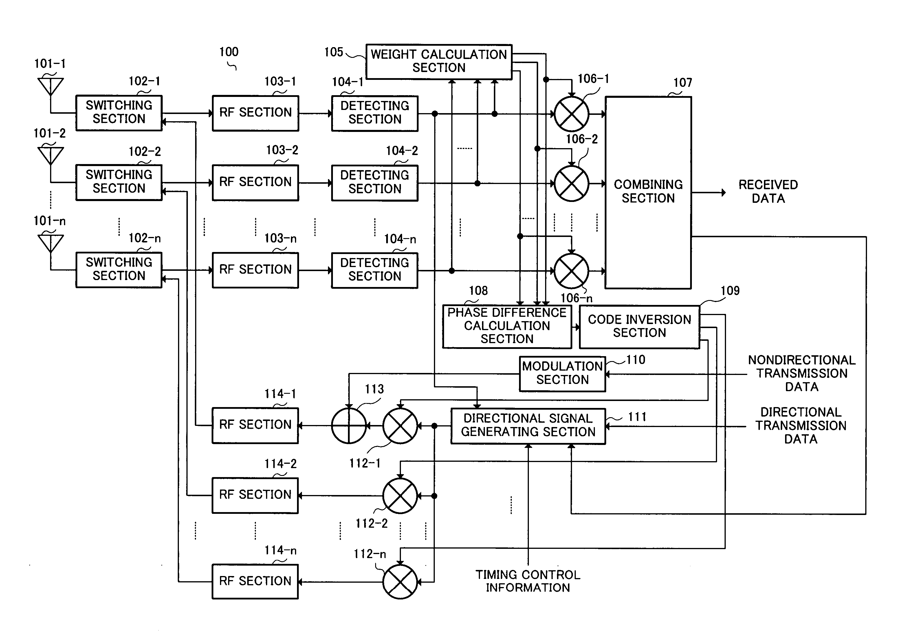
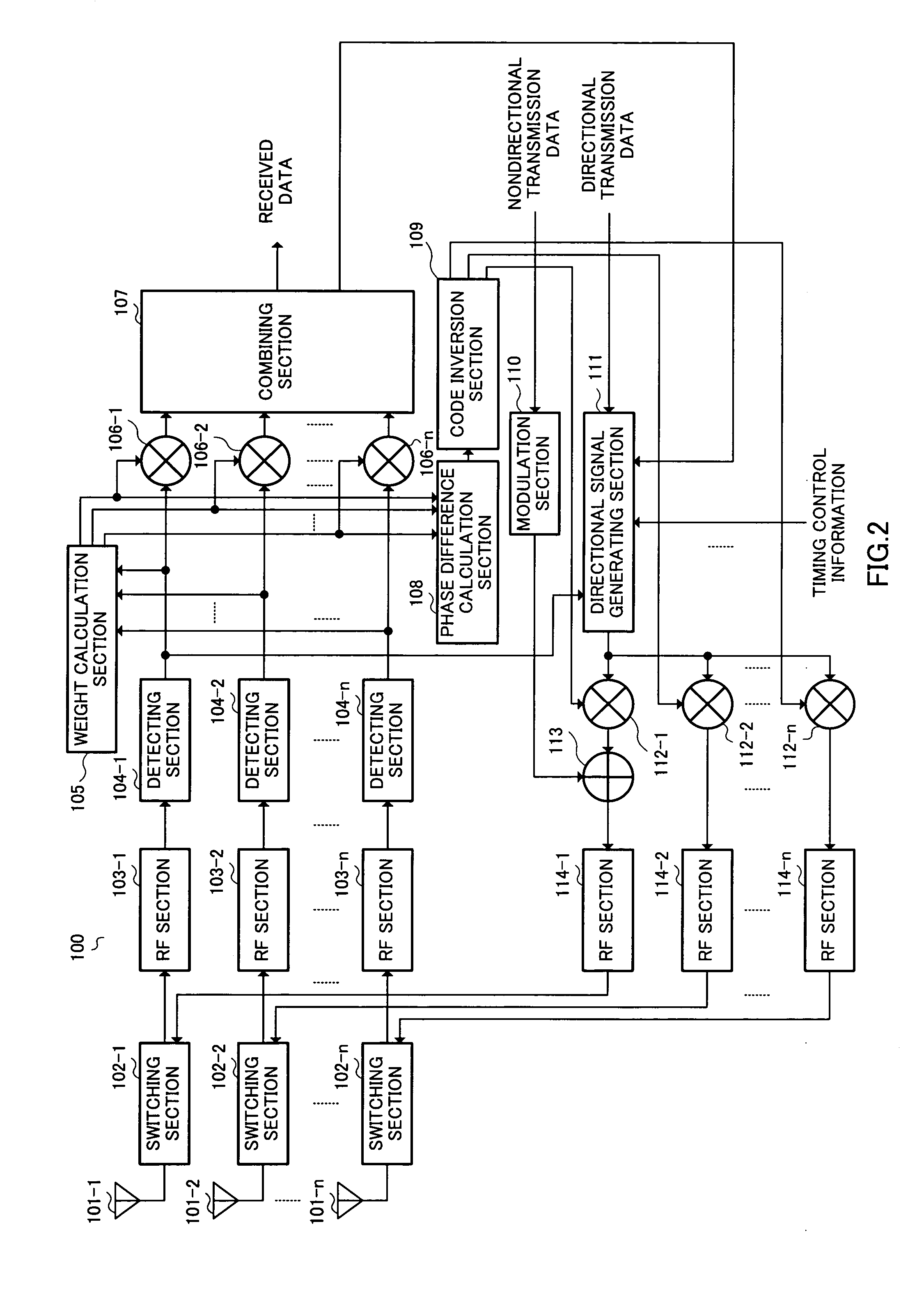
[0037]FIG. 2 is a block diagram showing a configuration of a transmission / reception apparatus according to Embodiment 1 of the present invention.
[0038] Switching sections 102-1 to 102-n switch between outputting received signals received at antennas 101-1 to 101-n to RF sections 103-1 to 103-n and transmitting transmission signals inputted from RF sections 114-1 to 114-n from antennas 101-1 to 101-n.
[0039] RF sections 103-1 to 103-n down-convert received signals inputted from switching sections 102-1 to 102-n from radio frequency to baseband frequency, and output the results to detecting sections 104-1 to 104-n.
[0040] Detecting section 104-1 performs quadrature detection on a received signal inputted from RF section 103-1 and outputs the quadrature detection result to weight calculation section 105 and multiplier 106-1. That is, detecting section 104-1 performs quadrature detection on a received signal inputted from RF section 103-1 and thereby outputs a complex baseband signal i...
embodiment 2
[0072]FIG. 6 is a block diagram showing a configuration of transmission / reception apparatus 500 according to Embodiment 2 of the present invention.
[0073] As shown in FIG. 6, a transmission / reception apparatus 500 according to Embodiment 2 of the present invention adds spreading section 501 to transmission / reception apparatus 100 according to Embodiment 1 shown in FIG. 2. In addition, parts in FIG. 6 that have identical configurations with ones in FIG. 2 will be assigned the same codes as in FIG. 2 without further explanations. Furthermore, a reception apparatus that is a communicating party of transmission / reception apparatus 500 has the same configuration as FIG. 4, and therefore the explanation thereof is omitted.
[0074] Spreading section 501 performs spreading processing on a nondirectional transmission signal inputted from modulation section 110 using predetermined spreading codes and outputs the result to adder 113.
[0075] Adder 113 is a code multiplex means and adds a directi...
embodiment 3
[0090]FIG. 10 is a block diagram showing a configuration of directional signal generating section 111 according to Embodiment 3 of the present invention.
[0091] As shown in FIG. 10, directional signal generating section 111 according to Embodiment 3 of the present invention has modulation section 901 in place of modulation section 202 and transmission level control section 903 in place of transmission level controls section 204, removes gain control signal generating section 201 and gain control signal multiplex section 203, and adds spreading section 902, in directional signal generating section 111 according to Embodiment 1 shown in FIG. 3. In addition, parts in FIG. 10 that have identical configurations with ones in FIG. 3 will be assigned the same codes as in FIG. 3 without further explanations. Configurations of a transmission / reception apparatus and a reception apparatus that is a communicating party of a transmission / reception apparatus has the same configurations as FIG. 2 a...
PUM
 Abstract
Description
Claims
Application Information
 - R&D Engineer
- R&D Manager
- IP Professional
- Industry Leading Data Capabilities
- Powerful AI technology
- Patent DNA Extraction
Browse by: Latest US Patents, China's latest patents, Technical Efficacy Thesaurus, Application Domain, Technology Topic.
© 2024 PatSnap. All rights reserved.Legal|Privacy policy|Modern Slavery Act Transparency Statement|Sitemap