Roll

a roll and rolling pin technology, applied in the field of rolling pins, can solve the problems of slipping rings in relation to each other, inferior friction between such surfaces, etc., and achieve the effects of improving friction joints, simple elements, and strong and efficient friction joints

Inactive Publication Date: 2006-12-21
SANDVIK INTELLECTUAL PROPERTY AB
View PDF13 Cites 4 Cited by
  • Summary
  • Abstract
  • Description
  • Claims
  • Application Information

AI Technical Summary

Benefits of technology

[0005] The present invention aims at obviating the above-mentioned disadvantages of previously known combi rolls and at providing an improved roll. Therefore, a primary object of the invention is to provide a combi roll in which large torque may be transmitted between adjacent rings via friction joints that in a reliable way counteract slipping between the rings. In other words, the invention aims at providing powerful and efficient friction joints between the rings of the roll. It is also an object to provide the improved friction joints by simple elements.

Problems solved by technology

Dependent on the surface finish and the nature of the different materials, the friction between such surfaces may become inferior, something that may lead to the rings slipping in relation to each other.

Method used


Image

  • Roll
  • Roll

Examples


Embodiment Construction

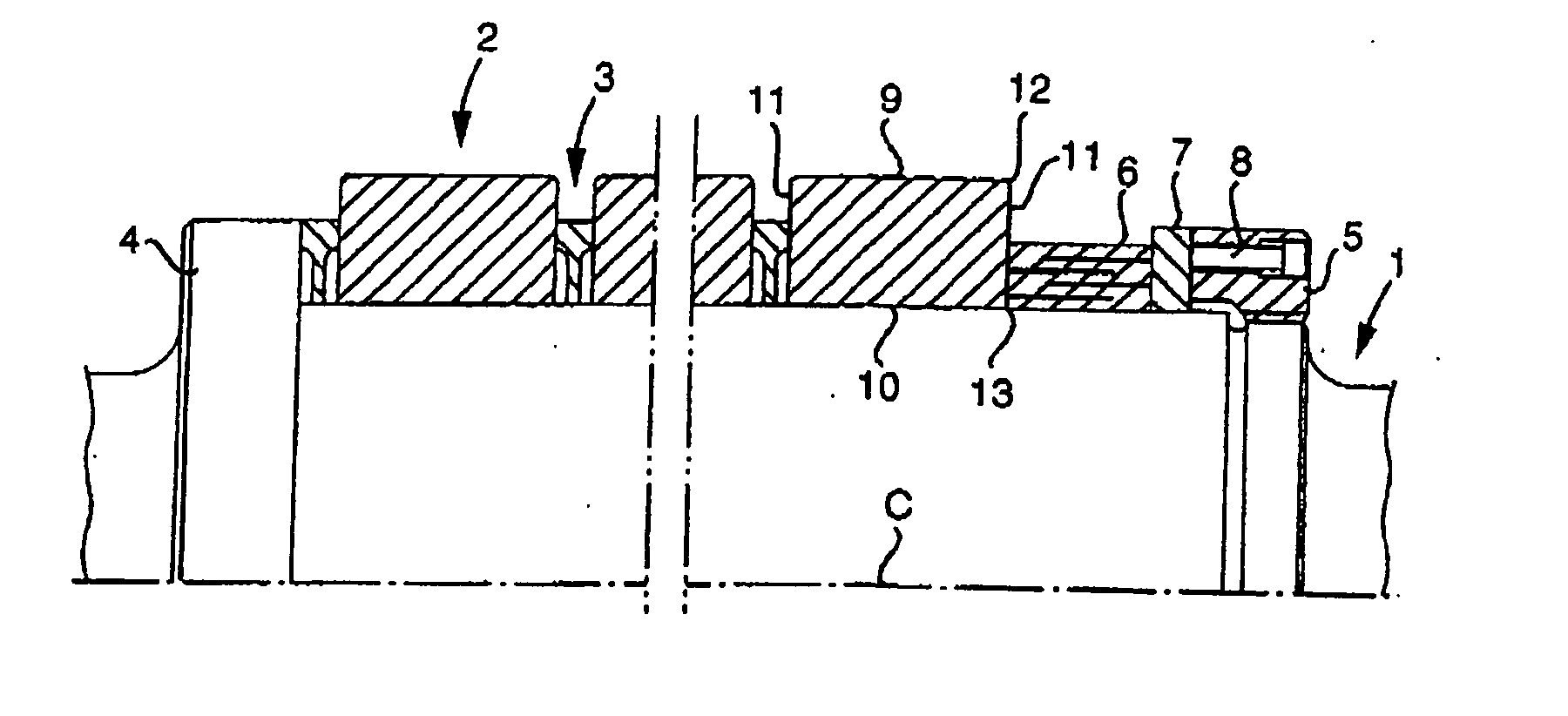
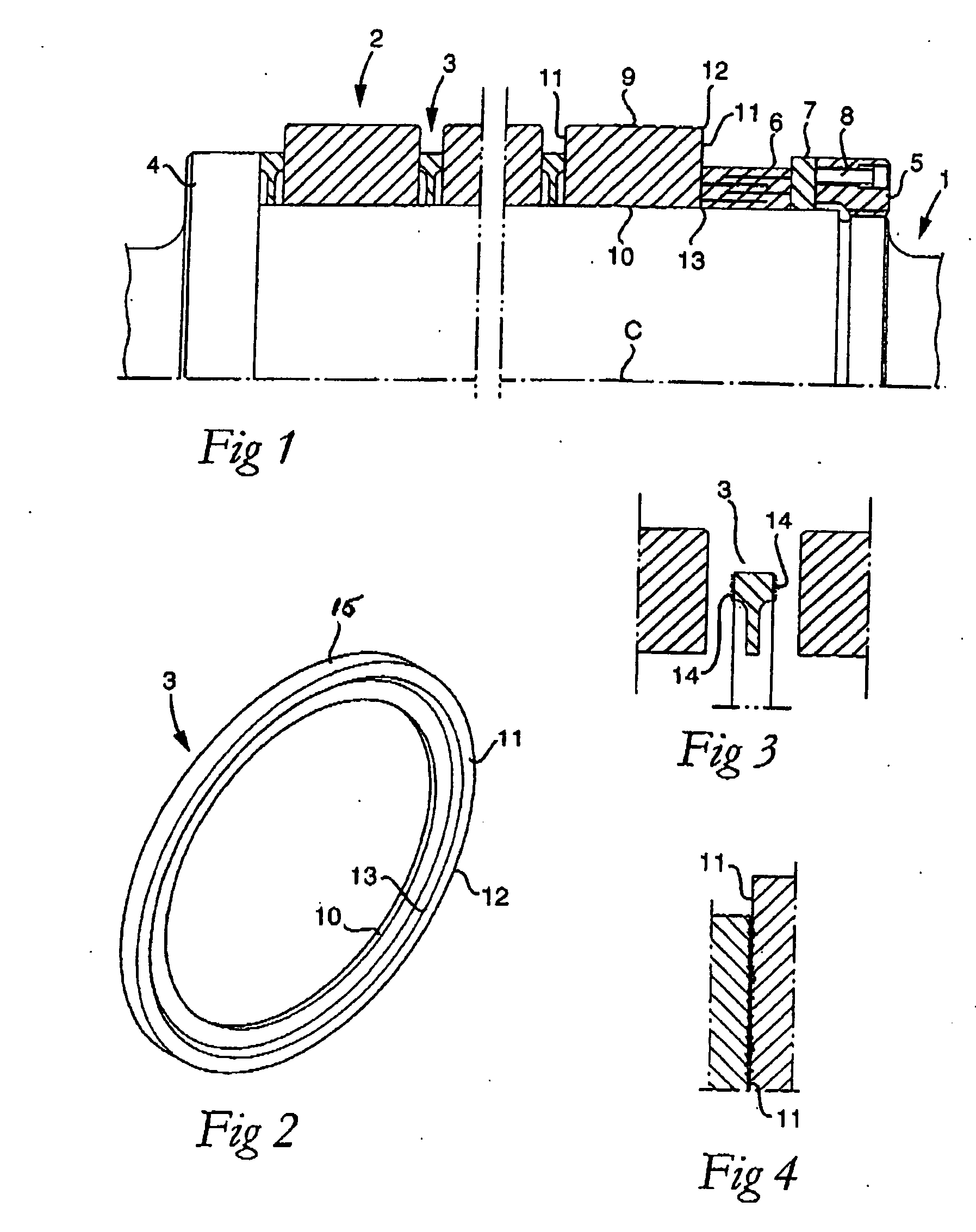
[0012] In FIG. 1, a roll is shown that includes a drivable roll shaft 1, a number of roll rings 2, and a number of spacer rings 3. The roll shaft 1 has a rotationally symmetrical basic shape defined by a center axis C.

[0013] The set of rings 2, 3 is kept in place between a fixed stop ring 4, which in the example is in the form of a ring-shaped shoulder, and a lock nut 5 at the opposite end of the shaft. The lock nut 5 has an internal thread (not shown), which may be tightened on an external thread of the roll shaft. Between the lock nut 5 and the first roll ring 2, there is in this case also a dynamic spring 6, which is separated from the lock nut by a ring 7. Furthermore, in the lock nut, there are a number of peripherically spaced-apart adjusting devices 8, by way of which the spring force of the spring 6 may be adjusted.

[0014] In the example, the roll rings 2 are assumed to be composed of solid cemented carbide, while the spacer rings 3 consist of a softer metal, e.g., steel. E...


PUM

PropertyMeasurementUnit
grain sizeaaaaaaaaaa
viscousaaaaaaaaaa

Abstract

A combi roll comprising a roll shaft and a roll ring mounted on the same against which at least one other ring is axially pressed, such as a spacer ring, the contact surfaces of the rings pressed against each other serving as torque-transferring friction joints. In the individual interface between two end contact surfaces there is distributed a great number of small grains of a material harder than the hardest material of anyone of the rings, the grains having the purpose of partially penetrating into each one of the contact surfaces so as to increase the torque-transferring ability of the friction joint.

Description

FIELD OF THE INVENTION [0001] The present invention relates to a combi roll comprising a roll shaft and a roll ring mounted on the same against which at least one other ring is axially pressed, end contact surfaces of the rings pressed against each other serving as torque-transferring friction joints. BACKGROUND OF THE INVENTION [0002] Generally, combi rolls include two or more roll rings, which are kept separated by intermediate spacer rings, the entire set of rings being kept fixed on the roll shaft by way of, on one hand, a fixed stop ring, e.g., a shoulder of the roll shaft and, on the other hand, a lock nut, which via an internal thread may be tightened on a male thread of the shaft. Furthermore, between the lock nut and the set of roll rings and spacer rings, respectively, springs as well as additional rings may be present. [0003] In many cases, the roll rings are manufactured from a hard material, such as cemented carbide, while intermediate spacer rings are manufactured of a...

Claims


Application Information

Patent Timeline
Patent Type & Authority Applications(United States)
IPC IPC(8): F16C13/00
CPCB21B27/035F16C13/00
Inventor KAYHAN, MENDERESANKARGREN, JIMMY
Owner SANDVIK INTELLECTUAL PROPERTY AB
Why Eureka
Try Eureka