Artificial chordae

a technology of artificial chords and chords, applied in the field of artificial chords, can solve the problems of mechanical valve use that typically requires extensive anticoagulation therapy, failure of such bioprostheses, and in need of reconstruction,

a technology of artificial chords and chords, applied in the field of artificial chords, can solve the problems of mechanical valve use that typically requires extensive anticoagulation therapy, failure of such bioprostheses, and in need of reconstruction,

US20060287716A1Inactive Publication Date: 2006-12-21THE CLEVELAND CLINIC FOUND

Image

  • Artificial chordae
  • Artificial chordae
  • Artificial chordae

Examples


Embodiment Construction

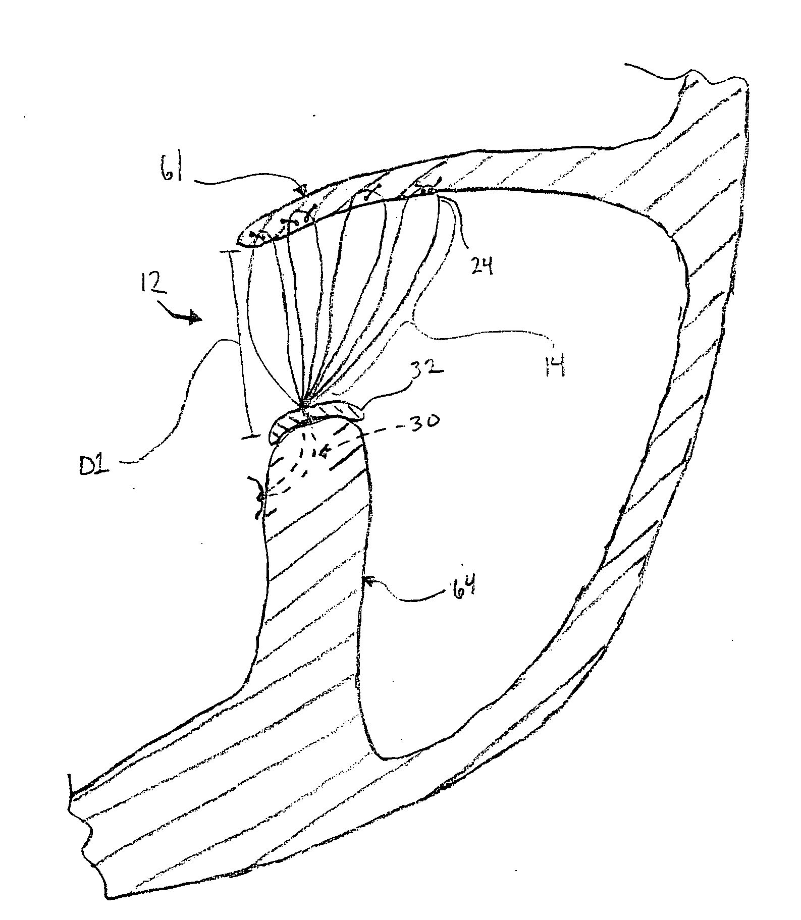
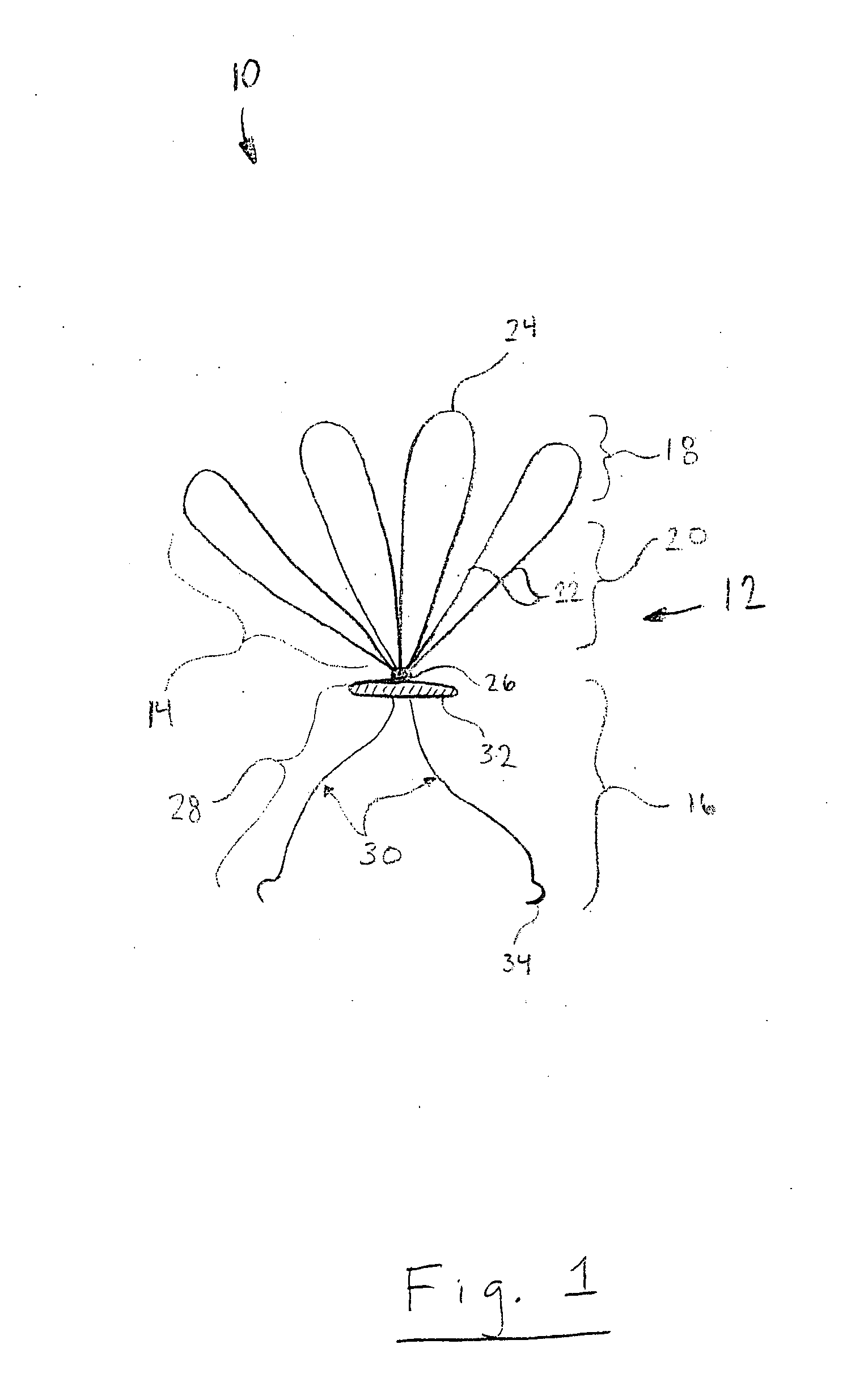
[0013] The present invention relates to artificial chordae, and more particularly to a prosthetic chordae assembly for a mitral or tricuspid valve. As representative of the present invention, FIG. 1 illustrates an apparatus 10 for replacing the native chordae 48 of a heart valve 59 having at least two leaflets 61 (FIG. 3). The apparatus 10 of the present invention comprises a prosthetic chordae assembly 12 (FIG. 1) configured to extend from a papillary muscle 64 (FIG. 3) to one of the at least two valve leaflets 61 of the heart valve 59. The prosthetic chordae assembly 12 (FIG. 1) comprises a plurality of loop members14, and has a first end portion 16, a second end portion 18, and a middle portion 20 extending between the end portions.

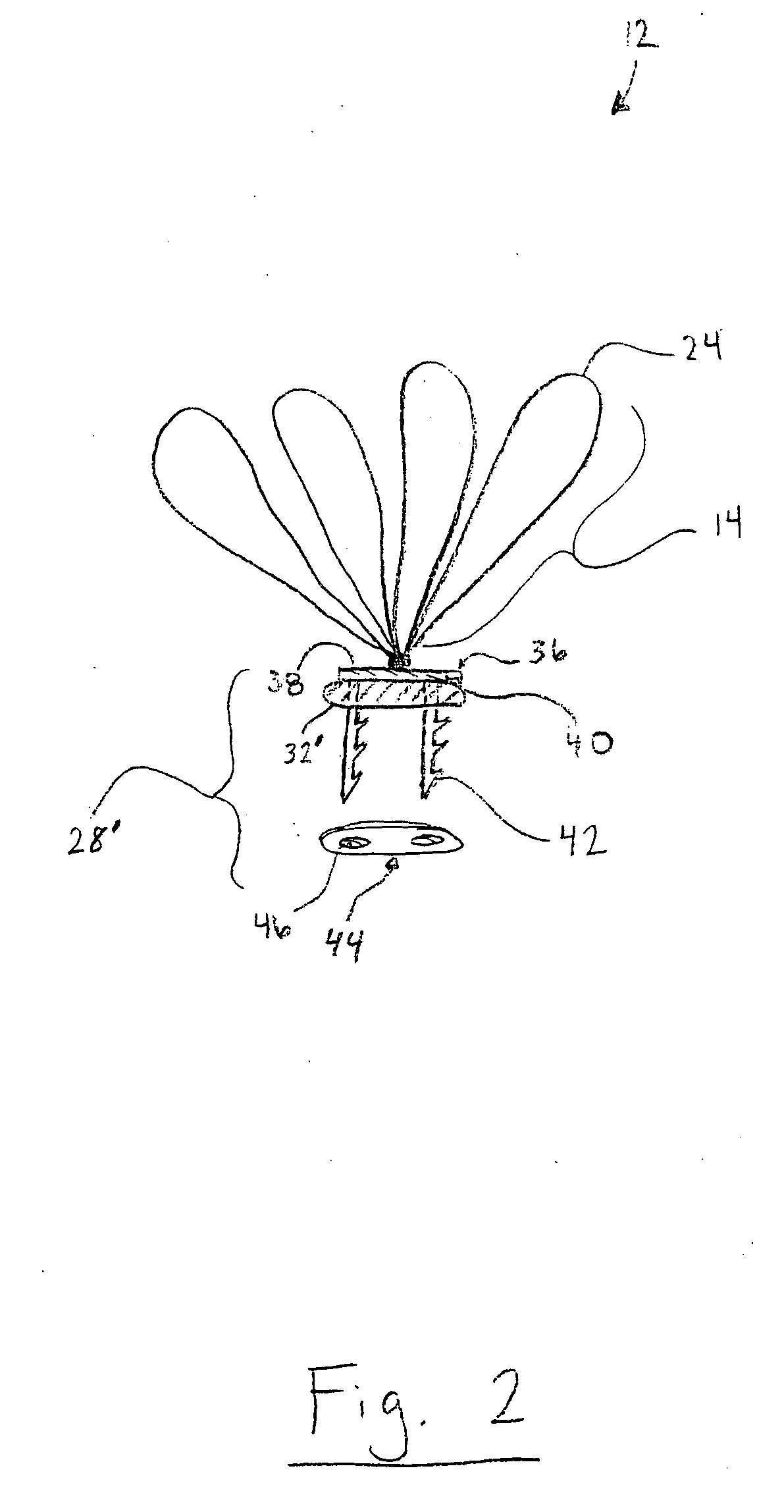
[0014] Each of the loop members 14 of the prosthetic chordae assembly 12 comprise two generally parallel strands 22 and an arcuate junction 24. The two generally parallel strands 22 are fluidly connected to the arcuate junction 24 of each loop member ...


PUM


Abstract

An apparatus for replacing the native chordae of a heart valve having at least two leaflets includes a prosthetic chordae assembly configured to extend from a papillary muscle to one of the at least two valve leaflets of the heart valve. The prosthetic chordae assembly has first and second end portions, and a middle portion extending therebetween. The prosthetic chordae assembly further includes a plurality of loop members interconnected at the first end portion for suturing to the papillary muscle. The middle portion is formed by two generally parallel strands of each of the loop members, and the second end portion is formed by an arcuate junction of the two strands of each of the loop members. The arcuate junctions are spaced apart and each of the junctions provides an independent location for attaching to one of the at least two valve leaflets of the heart valve.

Description

RELATED APPLICATION [0001] This application claims priority from U.S. provisional patent application Ser. No. 60 / 688,455, filed Jun. 8, 2005, the subject matter of which is incorporated herein by reference.TECHNICAL FIELD [0002] The present invention relates to artificial chordae, and more particularly to a prosthetic chordae assembly for a mitral or tricuspid valve. BACKGROUND OF THE INVENTION [0003] Heart valve replacement is a well known procedure in which an artificial heart valve prosthesis is implanted in place of a diseased or malfunctioning heart valve. Heart valve prostheses may be mechanical or bioprosthetic. Use of mechanical valves typically requires extensive anticoagulation therapy. The need for anticoagulation therapy can be avoided in general by the use of artificial biological heart valves, such as bovine xenografts. Nevertheless, dystrophic calcification with subsequent degeneration is the major cause of failure of such bioprostheses in the long term. [0004] When m...

Claims


Application Information

Patent Timeline
21 Dec 2006
Publication
US20060287716A1
IPC
A61F2/24
CPC
A61F2/2457
Inventors
BANBURY, MICHAEL K.; GILLINOV, A. MARC