X-ray CT method and X-ray CT apparatus

a ct method and x-ray cone technology, applied in tomography, applications, instruments, etc., can solve the problems of limited number of slices, limited free choice in designating radiographic conditions in relation to one rotational radiation of x-ray cone beams, and limited optimization of radiographic conditions, so as to achieve the effect of optimizing radiographic conditions

Inactive Publication Date: 2006-12-28
GE MEDICAL SYST GLOBAL TECH CO LLC
View PDF22 Cites 155 Cited by
  • Summary
  • Abstract
  • Description
  • Claims
  • Application Information

AI Technical Summary

Benefits of technology

[0015] Therefore, an object of the present invention is to provide an X-ray CT method and an X-ray CT apparatus making it possible to optimize radiographic conditions for a conventional scan or a cine scan of scanning one position in a z direction, which is performed by an X-ray CT apparatus including an X-ray area detector that has a matrix structure and that is represented by a conventional multi-array detector or a flat-panel X-ray detector, in relation to one rotational irradiation of an X-ray cone beam, or making it possible to freely designate the radiographic conditions.
[0016] The present invention provides an X-ray CT method or an X-ray CT apparatus making it possible to optimize radiographic conditions or freely designate radiographic conditions in a case where an X-ray cone beam that spreads in a z direction is used to radiograph a wide range extending in the z direction during a conventional scan that requires one rotational irradiation of the X-ray cone beam or during a cine scan that images one position in the z direction.

Problems solved by technology

Moreover, freedom in designating the radiographic condition in relation to one rotational radiation of an X-ray cone beam is limited.
This poses a problem in terms of optimization of the radiographic condition.
However, since the number of slices is limited, the multi-slice scan for scanning thin slices is performed on slices separated from one another.
This is inefficient.
However, an idea that a plurality of organs is radiographed by diversifying a radiographic method during one irradiation of an X-ray cone beam has not been proposed.

Method used


Image

  • X-ray CT method and X-ray CT apparatus
  • X-ray CT method and X-ray CT apparatus
  • X-ray CT method and X-ray CT apparatus

Examples


Embodiment Construction

[0074] Referring to appended drawings, the best mode for implementing an X-ray CT method and an X-ray CT apparatus in accordance with the present invention will be described below. Noted is that the present invention will not be limited to the best mode.

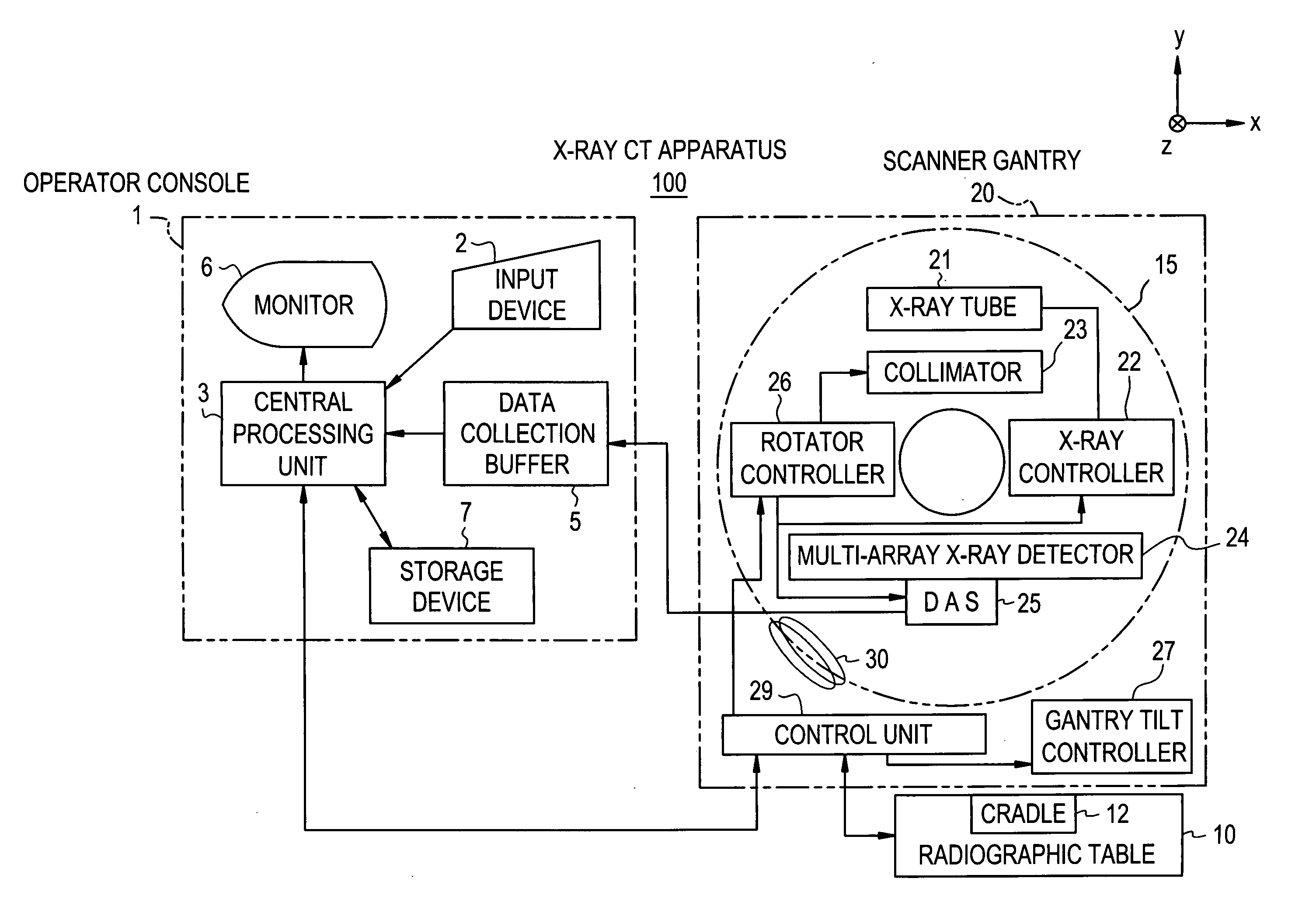
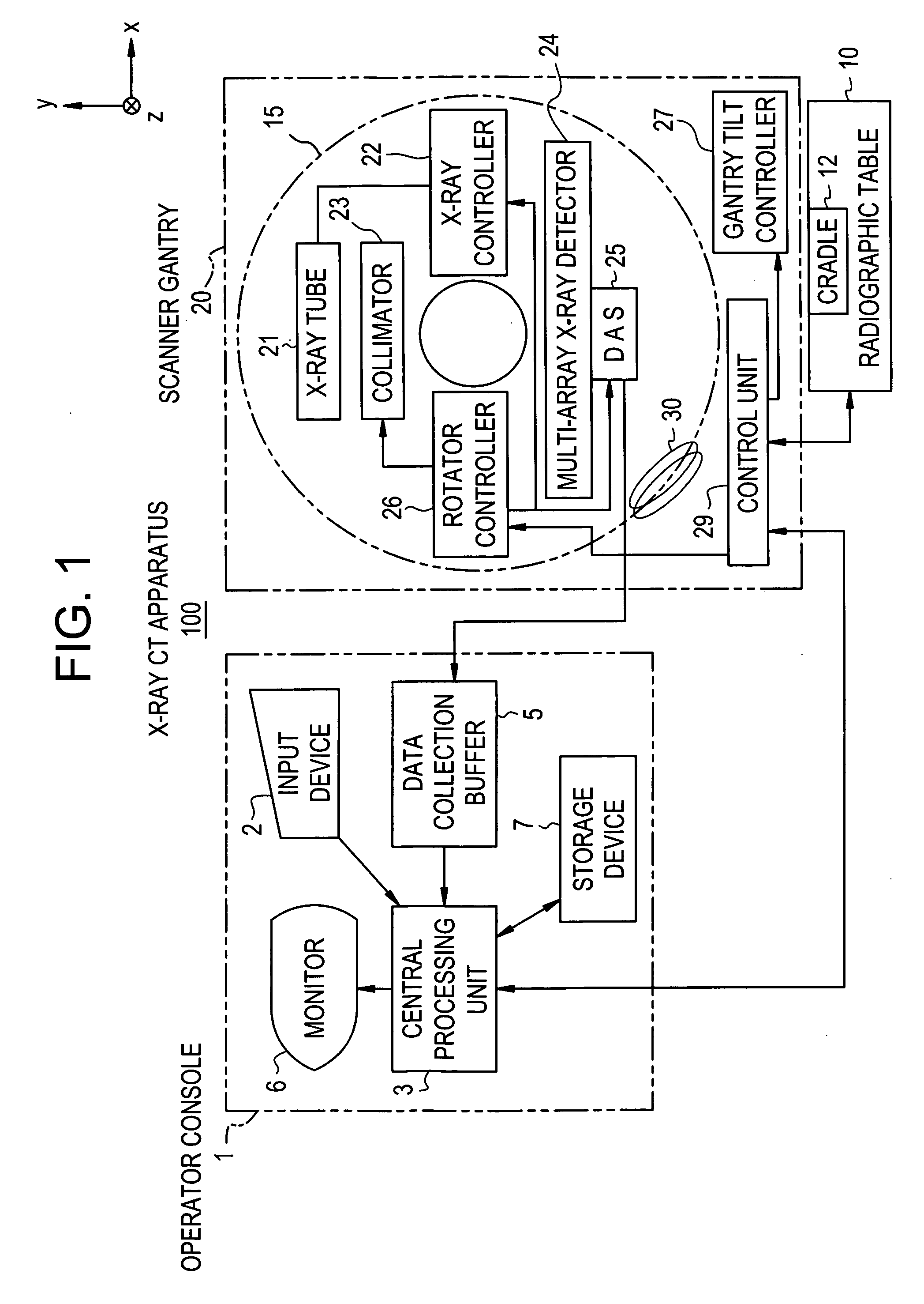
[0075]FIG. 1 is a block diagram showing the overall configuration of an X-ray CT apparatus in accordance with an embodiment of the present invention. The X-ray CT apparatus 100 includes an operator console 1, a radiographic table 10, and a scanner gantry 20.

[0076] The operator console 1 includes an input device 2 that receives an operator's input, a central processing unit 3 that includes an image reconstruction means for executing preprocessing, image reconstruction, and post-processing, a data collection buffer 5 into which X-ray detector data acquired by the scanner gantry 20 is collected, a monitor 6 that is an image display means on which a tomographic image reconstructed based on X-ray projection data produced by preprocessin...


PUM

PropertyMeasurementUnit
thicknessaaaaaaaaaa
thicknessaaaaaaaaaa
widthaaaaaaaaaa

Abstract

In an X-ray CT apparatus, radiographic conditions (protocols) for imaging of each position represented by a z-coordinate are optimized in relation to an X-ray cone beam that spreads in a z direction. A slice thickness of a tomographic image is freely controlled in the z direction using a z filter during a conventional scan or a cine scan. For each tomographic image, a reconstruction function, an image filter, a scan field, a tomographic-image tilt angle, and a position of a tomographic image are freely adjusted or independently designated for scanning of each position in the z direction. Thus, a tomographic image is reconstructed. Moreover, the position of a beam formation X-ray filter in the z direction is shifted in order to optimize a patient dose that depends on the size of the scan field, and X-ray quality.

Description

CROSS REFERENCE TO RELATED APPLICATIONS [0001] This application claims the benefit of Japanese Application No. 2005-184720 filed Jun. 24, 2005. BACKGROUND OF THE INVENTION [0002] The present invention relates to an X-ray CT method and an X-ray CT apparatus in which radiographic conditions for a conventional scan or a cine scan are designated. [0003] In X-ray CT apparatuses including an X-ray area detector represented by a multi-array X-ray detector or a flat-panel X-ray detector, only one set of radiographic conditions (protocols) is designated for a conventional scan (which may be called an axial scan) for which X-rays are rotationally irradiated once or a cine scan that holds a subject immobile at one scanned position. Moreover, freedom in designating the radiographic condition in relation to one rotational radiation of an X-ray cone beam is limited. This poses a problem in terms of optimization of the radiographic condition. [0004]FIG. 20 shows an X-ray data acquisition assembly ...

Claims


Application Information

Patent Timeline
Patent Type & Authority Applications(United States)
IPC IPC(8): H05G1/60A61B6/00G01N23/00G21K1/12
CPCA61B6/032A61B6/4085A61B6/027A61B6/488A61B6/469A61B6/03
Inventor NISHIDE, AKIHIKOIMAI, YASUHIRO
Owner GE MEDICAL SYST GLOBAL TECH CO LLC
Why Eureka
Try Eureka