Hearing aid comprising adaptive feedback suppression system

a technology of adaptive feedback and suppression system, which is applied in the field of hearing aids, can solve the problems of unstable output of hearing aid, once-inaudible acoustic feedback becoming audible, and the output of hearing aid generated within the ear canal can exceed the attenuation offered by the ear mould/shell, etc., and achieve the effect of fast gain adjustmen

Active Publication Date: 2006-12-28
WIDEX AS
View PDF4 Cites 63 Cited by
  • Summary
  • Abstract
  • Description
  • Claims
  • Application Information

AI Technical Summary

Benefits of technology

[0017] The adaptive equalization filter preferably comprises a plurality of multipliers for multiplying the frequency band signals with the gain factor signal generating the gain adjusted frequency band signal. The multipliers may be connected before or behind the corresponding bandpass filte

Problems solved by technology

But when in-situ gain of the hearing aid is sufficiently high or when a larger than optimal size vent is used, the output of the hearing aid generated within the ear canal can exceed the attenuation offered by the ear mould/shell.
The output of the hearing aid then becomes unstable and the once-inaudible acoustic feedback becomes audible, i.e. in the form of a whistling or howling noise.
For many users and people around, such audible acoustic feedback is an annoyance and even an embarrassment.
In addition, hearing instruments that are at the verge of howling, i.e. show sub-oscillatory feedback, may corrupt the frequency characteristic and may exhibit intermittent whistling.
Acoustic feedback is in particular an important problem in CIC (Complete In the Canal) hearing aids with a vent opening since the vent opening and the short distance between the output and the input transducers of the hearing aid lead to a low attenuation of the acoustic feedback path from the output transducer to the input transducer, and the short delay time maintains correlation in the signal.
Thus, the adaptive fil

Method used


Image

  • Hearing aid comprising adaptive feedback suppression system
  • Hearing aid comprising adaptive feedback suppression system
  • Hearing aid comprising adaptive feedback suppression system

Examples


Embodiment Construction

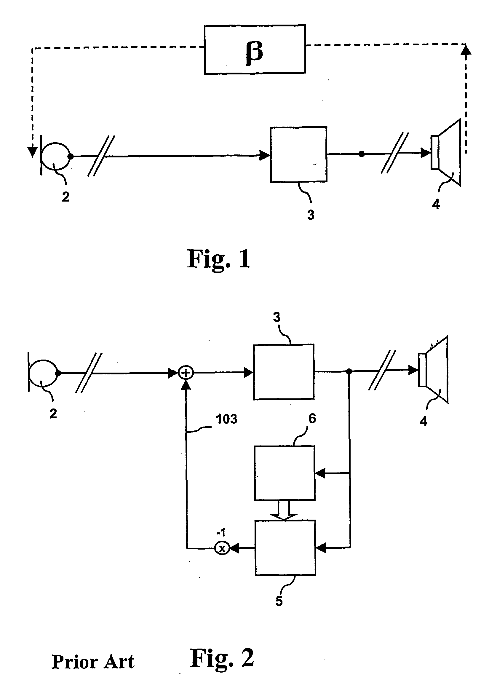
[0033]FIG. 1 shows a simple block diagram of a hearing aid comprising an input transducer or microphone 2 transforming an acoustic input into an electrical input signal, a signal processor or compressor 3 amplifying the input signal and generating a processor output signal and finally an output transducer or receiver 4 for transforming the processor output signal into an acoustic output. The acoustic feedback path of the hearing aid is depicted by broken arrows, whereby the attenuation vector is denoted by β. If, in a certain frequency range, the product of the gain G (including transformation efficiency of microphone and receiver) of the processor 3 and the attenuation β is close to 1, audible acoustic feedback occurs.

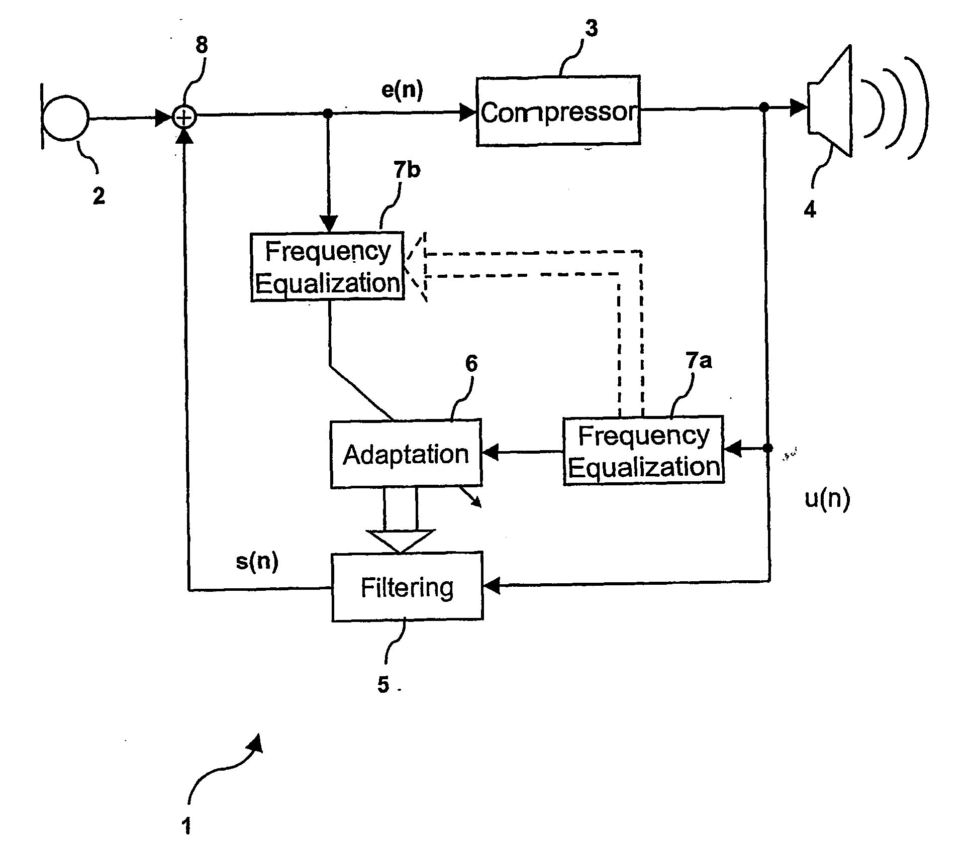
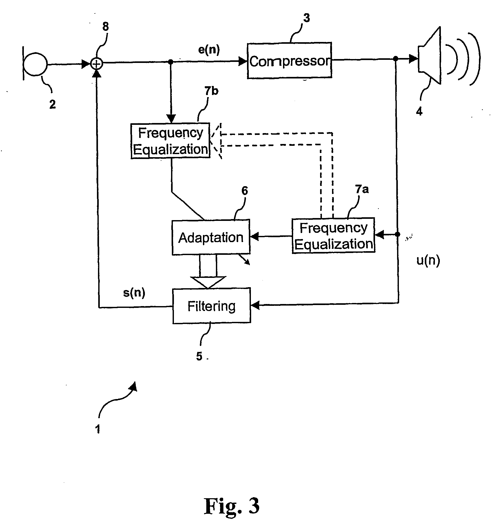
[0034]FIG. 2 shows an adaptive feedback suppression system schematically. The output signal from signal processor 3 (reference signal) is fed to an adaptive estimation filter 5. A filter control unit 6 controls the adaptive filter, e.g. the convergence rate or speed ...


PUM


Abstract

A hearing aid comprises an input transducer (2), a subtraction node for subtracting a feedback cancellation signal from the electrical input signal thereby generating a processor input signal, a signal processor (3), an output transducer (4), a pair of equalization filters (7a, 7b) for selecting from the processor input and output signals a plurality of frequency band signals, a frequency equalization unit for frequency equalization for the selected frequency band signals, and an adaptive feedback estimation filter (5, 6) for adaptively deriving the feedback cancellation signal from the equalized frequency band signals. The equalization of selected frequency bands of the input signals of the adaptive feedback cancellation filter provides for an improved and in particular a faster adaption of the feedback cancellation. The invention further provides a method of reducing acoustic feedback of a hearing aid, and a hearing aid circuit.

Description

RELATED APPLICATIONS [0001] The present application is a continuation-in-part of application no. PCT / EP2004 / 002135, filed on Mar. 3, 2004, with The European Patent Office and published as WO 2005 / 096670 A1.BACKGROUND OF THE INVENTION [0002] 1. Field of the Invention [0003] The invention relates to the field of hearing aids. The invention, more specifically, relates to a hearing aid having an adaptive filter for generating a feedback cancellation signal, to a method of reducing acoustic feedback of a hearing aid and to a hearing aid circuit. [0004] 2. The Prior Art [0005] Acoustic feedback occurs in all hearing instruments when sounds leak from the vent or seal between the ear mould and the ear canal. In most cases, acoustic feedback is not audible. But when in-situ gain of the hearing aid is sufficiently high or when a larger than optimal size vent is used, the output of the hearing aid generated within the ear canal can exceed the attenuation offered by the ear mould / shell. The out...

Claims


Application Information

Patent Timeline
IPC IPC(8): H04R25/00
CPCH04R25/453
Inventor KLINKBY, KRISTIAN TJALFENORGAARD, PETER MAGNUSCEDERBERG, JORGEN
Owner WIDEX AS
Why Eureka
Try Eureka