Object pattern detection method and its apparatus

a detection method and object technology, applied in the field of object pattern detection methods, can solve problems such as erroneous detection and occurrence in the vote space, and achieve the effect of reducing the occasions of non-object pattern detection and high detection ra

Inactive Publication Date: 2006-12-28
KK TOSHIBA
View PDF2 Cites 16 Cited by
  • Summary
  • Abstract
  • Description
  • Claims
  • Application Information

AI Technical Summary

Benefits of technology

[0012] According to embodiments of the present invention, occasions of detect

Problems solved by technology

In the above method, even for a pattern other than the object pattern, a

Method used


Image

  • Object pattern detection method and its apparatus
  • Object pattern detection method and its apparatus
  • Object pattern detection method and its apparatus

Examples


first embodiment

(1) Construction of Pattern Detection Apparatus

[0042] In this embodiment, a pattern detection apparatus shown in a block diagram of FIG. 10 is used. The pattern detection apparatus includes a transformation parameter adder 1004, a transformation parameter vote buffer 1006, and an output parameter determiner 1007.

[0043] The transformation parameter adder 1004 receives, as inputs, a binary bitmap 1002 of an object region and a non-object region and a contour candidate point 1003, and collates them against a template 1001 of a previously registered binary bitmap to detect an object pattern. The output parameter determiner 1007 outputs a transformation parameter.

(2) Pattern Detection Method by Introduction of Two-Level or Binary Bitmap

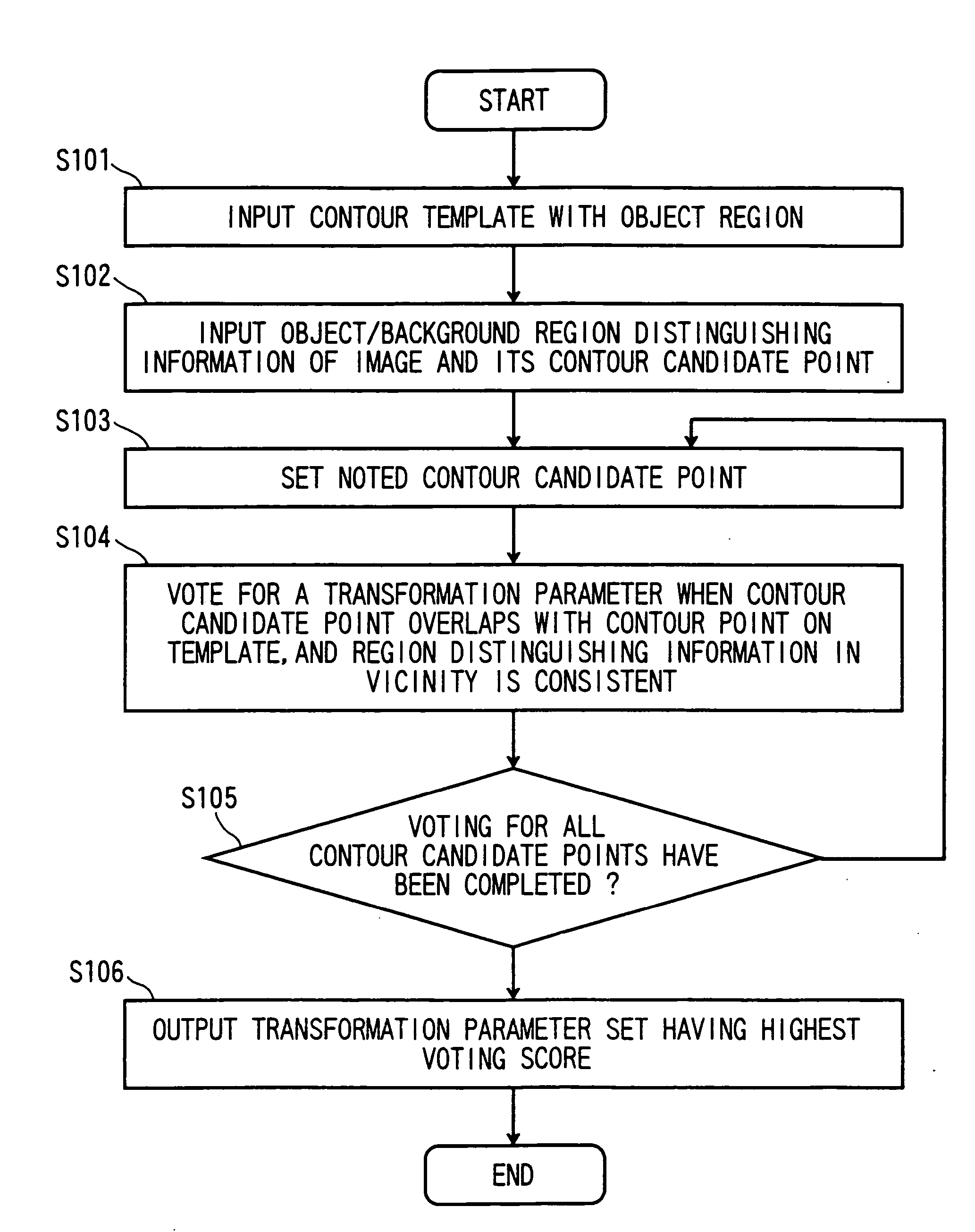
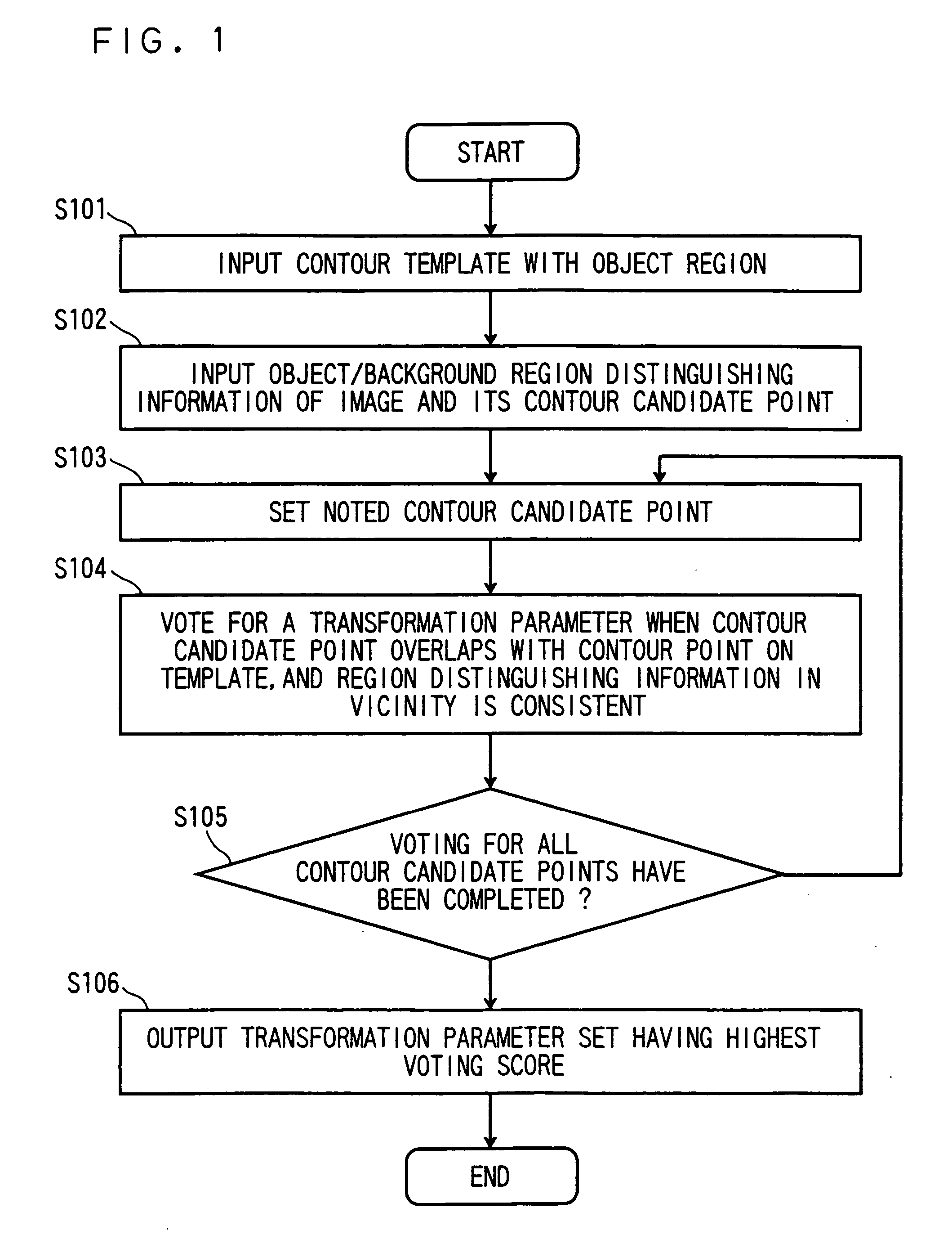
[0044] The embodiment of a pattern detection method using a binary bitmap of an object region and a non-object region will be described with reference to a flowchart of FIG. 1.

[0045] The transformation parameters may be; for example, (n+1) values to...

second embodiment

[0083] In a second embodiment, a weighting value is assigned to each contour point on the template.

[0084] In the foregoing first embodiment, in the case where the contour candidate point of the image overlaps with the contour point of the template, voting value of 1 is added to the histogram at each voting. However, irrespective of whether the two-level binary bitmap is introduced or not, the contour points of the template include; a point where it is highly probable that the contour candidate point of the object is identical to the contour point of the template when overlapping between the contour point and the contour candidate point occurs; and a point which has low reliability of identicalness even if the overlapping occurs.

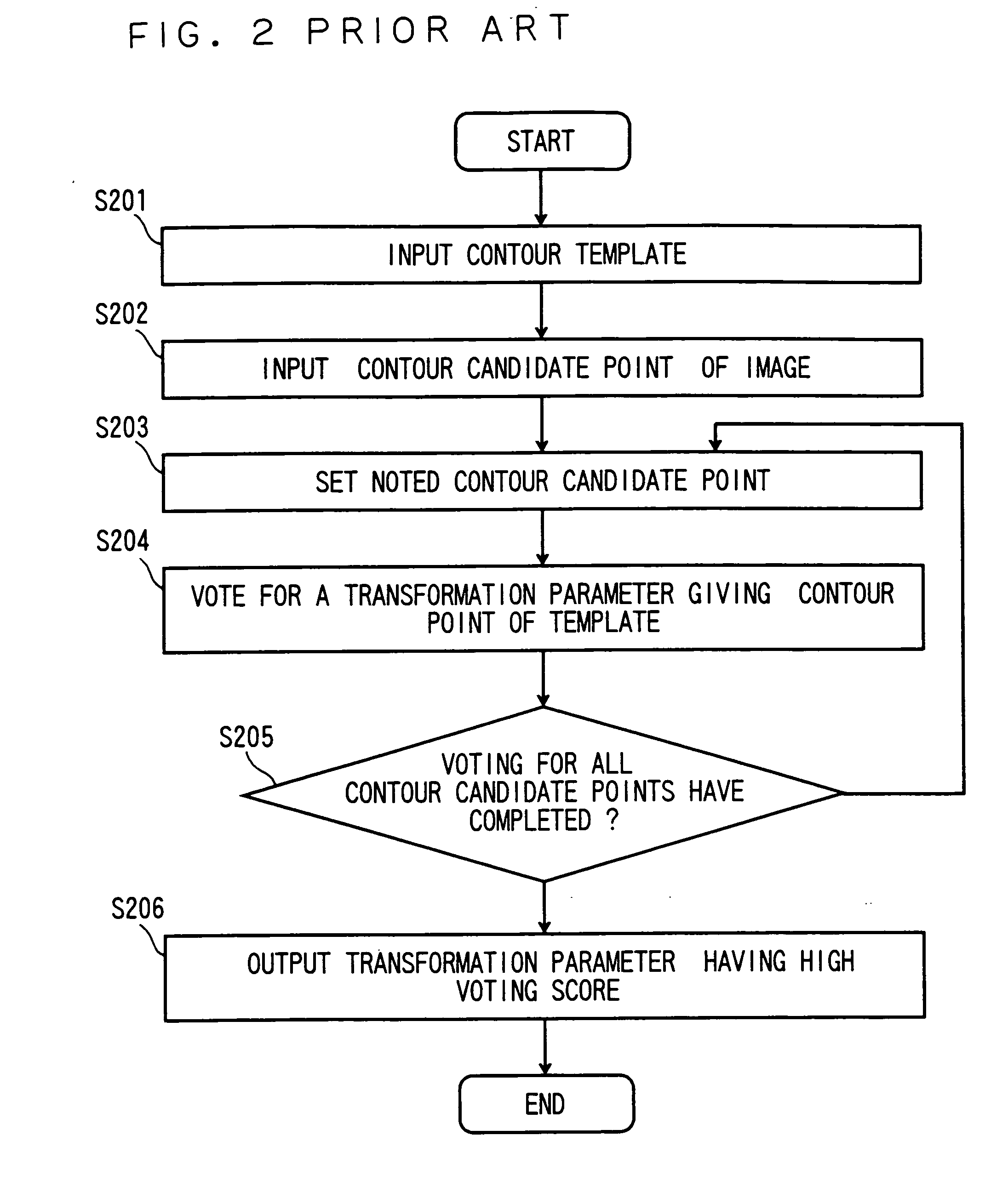
[0085] In the conventional method, since voting value of 1 is always added without considering the reliability of the contour point, the detection may become difficult depending on the shape of the template.

[0086] For example, as shown in FIG. 9, in the ca...

third embodiment

[0095] In a third embodiment, a weighting value is assigned to each contour candidate point on an image that is obtained by the edge detection or the like.

[0096] In the foregoing second embodiment, the weighting value is assigned to each of the contour points of the template. The same way of the assigning may be made to a contour candidate point of an image.

[0097] In the heretomentioned embodiments, the contour candidate point of the image is obtained by binarization after the edge detection, or is obtained based on the binary bitmap obtained by the difference method. In the edge detection, probability of being a contour is calculated; and in the difference method, probability of being an object region is calculated. When the value to be added is controlled or adjusted using such probability, the detection accuracy is improved. Hereinafter, the embodiment using such probability will be described.

[0098] A flowchart of this embodiment is as shown in FIG. 15.

[0099] While the flowch...


PUM


Abstract

A method to detect a given pattern in an image, as for obtaining, by a computer, transformation parameters that facilitate transformation of a template as to be overlapped with the object, comprising: inputting the template having contour points and region distinguishing information for each points; inputting contour candidate points and region distinguishing information for each points; transforming a position or a shape of the template by using each of transformation parameter set candidates; obtaining an evaluation value, or similarity of a distribution of the object and background regions, on each overlapping pair between one of the contour candidate points in the image and one of the contour points of the template; obtaining sum of the evaluation values only for those not smaller than a threshold evaluation value, for the each of the transformation parameter set candidates; and outputting a transformation parameter set having largest sum of the evaluation values.

Description

CROSS-REFERENCE TO RELATED APPLICATIONS [0001] This application is based upon and claims the benefit of priority from the prior Japanese Patent Application No. 2005-186998, filed on Jun. 27, 2005; the entire contents of which are incorporated herein by reference. TECHNICAL FIELD [0002] The invention relates to a method and an apparatus to detect an object pattern in an image when the pattern (for example, a shape pattern of an average person) to be detected is given on beforehand. BACKGROUND OF THE INVENTION [0003] As a method suitable for detection of an object, a generalized Hough transform disclosed by D. H. Ballard (“Generalizing the Hough Transform to Detect Arbitrary shapes”, Pattern Recognition Vol. 13, No. 2, pp. 111-122, 1981) is widely used in which a predetermined template “T” is detected from an image “S”. [0004] In this method, first, a template is inputted (S201 of FIG. 2), and a pixel on which an edge exists is obtained in an image “S” and is inputted (S202). [0005] N...

Claims


Application Information

Patent Timeline
IPC IPC(8): G06K9/62
CPCG06K9/6206G06K9/6204G06V10/752G06V10/754
Inventor TAKESHIMA, HIDENORIMASUKURA, KOICHIIDA, TAKASHI
Owner KK TOSHIBA
Why Eureka
Try Eureka