
Worklight support with stand

a worklight support and stand technology, applied in the direction of lighting support devices, lighting and heating apparatus, rod connections, etc., can solve the problems of time-consuming, labor-intensive, and inefficient loosening and tightening process of adjusting the worklight support, and achieve the effect of convenient disassembly of the worklight suppor

Inactive Publication Date: 2006-12-28
TSAI PETER
View PDF5 Cites 5 Cited by
  • Summary
  • Abstract
  • Description
  • Claims
  • Application Information

AI Technical Summary

Benefits of technology

[0006] The primary objective of the present invention is to provide a worklight support connected to a stand via couplers so that the user is able to readily disassemble the worklight support and the worklight stand.
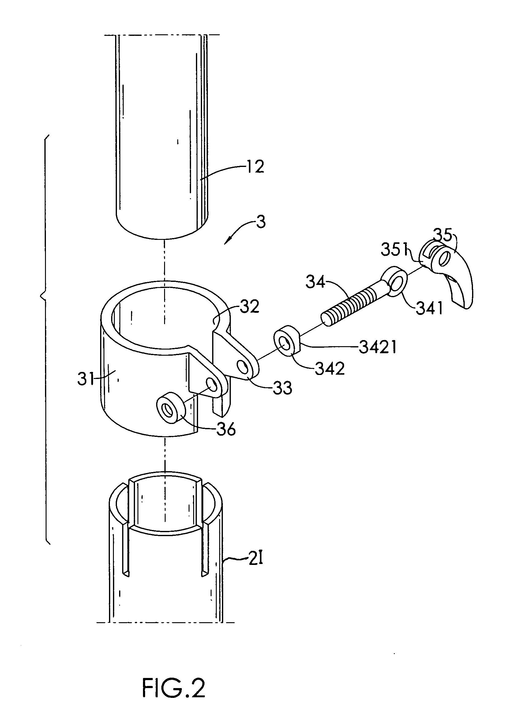
[0009] A further aspect of the present invention is that each stand section has an annular ring with a gap defined therein, two wings respectively extending from two opposed sides defining the gap to allow a threaded bolt to extend therethrough and a pivotal handle pivotally connected to the threaded bolt such that pivotal movement of the handle is able to narrow a diameter of the annular ring. Therefore, after the extension is extended and received in one of the stand section, the handle is able to secure the position of the extension relative to the corresponding stand section.

Problems solved by technology

The loosening and tightening process to adjust the worklight stand is not efficient and is time consuming especially in an emergency situation.
Therefore, it is a requirement for the user to unscrew the at least one screw (51) fixing the worklight support (5) on top of the worklight stand (6) when in disassembly thereof, which is quite labor inefficient.

Method used


Image

  • Worklight support with stand
  • Worklight support with stand
  • Worklight support with stand

Examples


Embodiment Construction

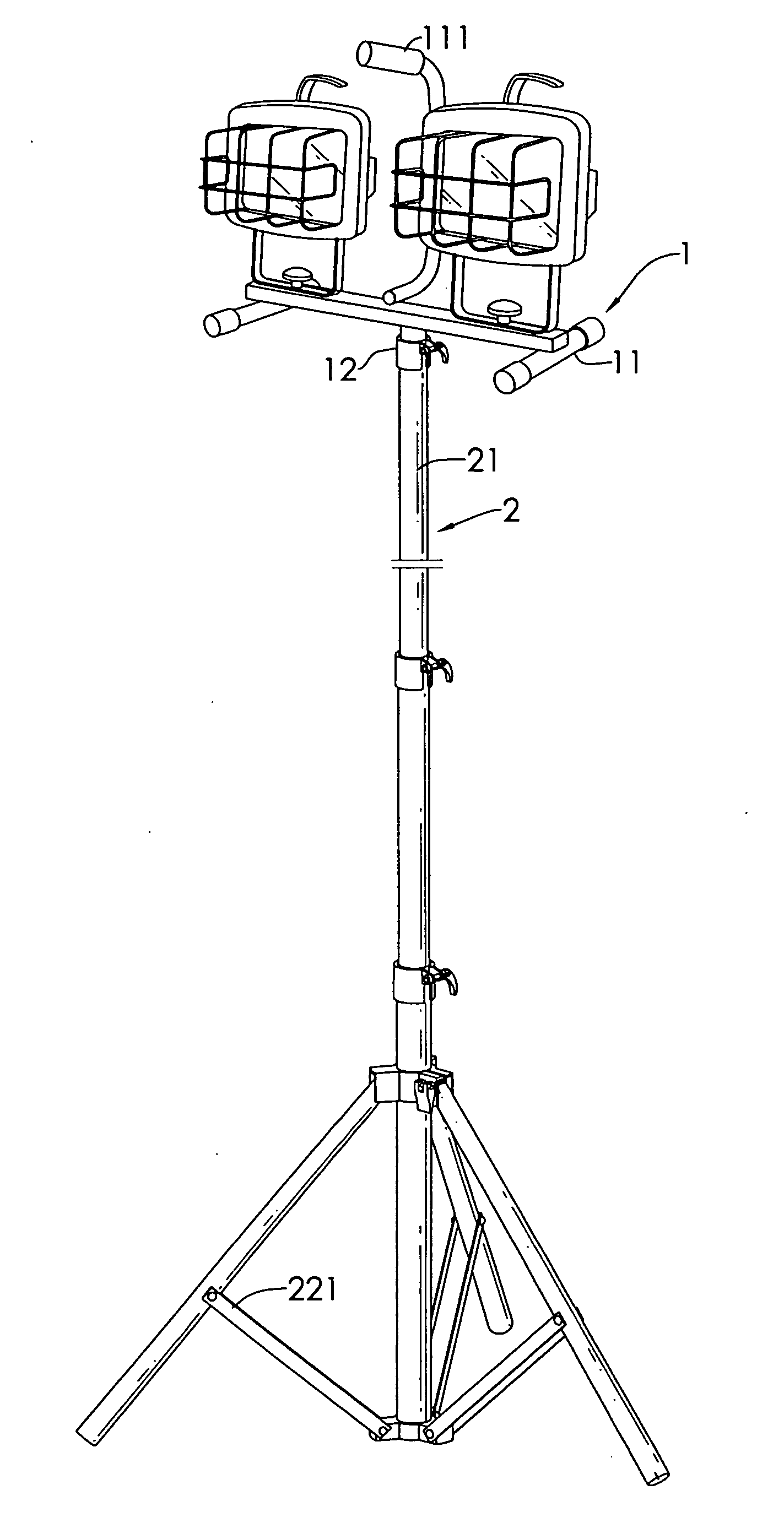
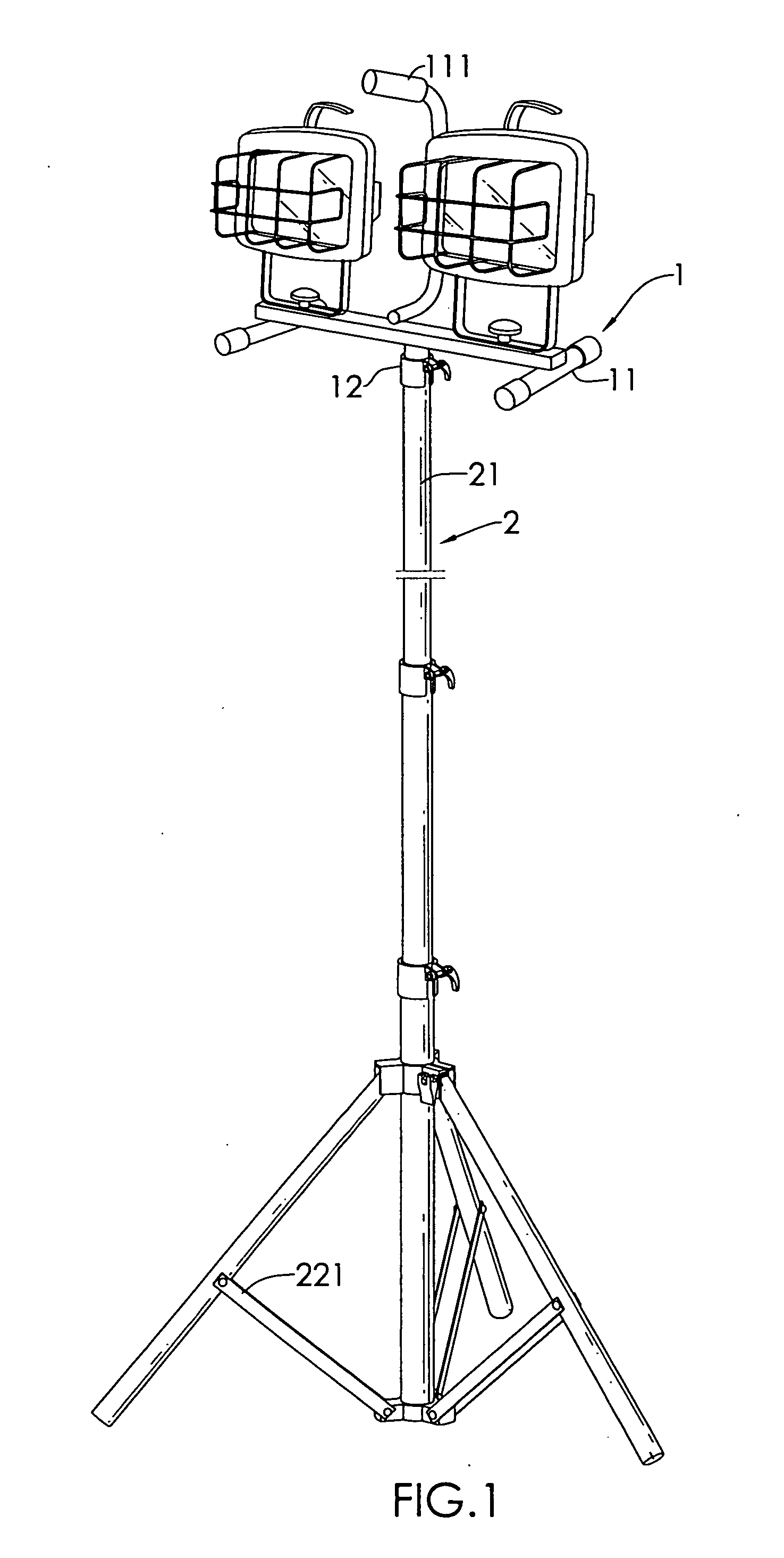
[0017] With reference to FIG. 1, it is noted that the worklight support (1) and the stand (2) of the present invention are shown. The worklight support (1) constructed in accordance with the present invention includes a platform (11) for mounting thereon worklights. The platform (11) has a handle (111) mounted thereon for easy transportation of the worklight support (1) and an extension (12) extending from a bottom face of the platform (11). The worklights shown on top of the platform (11) are for illustrative purpose only and not intended to limit the scope of the invention. The scope of the present invention should be determined by the claims.

[0018] With reference to FIGS. 2 and 3, it is noted that a coupler (3) is used to secure two adjacent stand sections of the worklight stand (2). Because telescopic sections interconnecting together are conventional in the art, the following description will not be discussing the structure of the telescopic sections of the worklight stand (2)...


PUM


Abstract

A worklight support includes a platform for mounting thereon worklights and has an extension extending from on a bottom of the platform for extension into one of the stand sections. A stand includes couplers applied for combination of each of the stand sections. Each coupler includes an annular ring for receiving therein a portion of one of the stand sections and a portion of the extension of the worklight support and a pivotal handle pivotally connected to the annular ring via a threaded bolt to selectively reduce an internal diameter of the annular ring to abut an outer periphery of the extension so as to fix the extension relative to one of the stand sections.

Description

BACKGROUND OF THE INVENTION [0001] 1. Field of the Invention [0002] The present invention relates to a worklight support with a stand, and more particularly to a worklight support having an extension extending downward therefrom and a stand telescopically connected to the worklight support. [0003] 2. Description of Related Art [0004] Worklights are extensively used in night working sites to provide illumination to workers. Normally, a single worklight assembly, as shown in FIG. 6, includes a support (5) for mounting thereon bulbs such as halogen lights and a stand (6) to provide stability to the support (5) on a surface. However, because the area that requires illumination changes a lot according to conditions, the height of the stand (6) changes to cope with the location variations. The conventional structure of the stand (6) includes multiple sections (60) and is telescopically connected together via rotating knobs (61) each provided at a joint of two adjacent sections (60) such t...

Claims


Application Information

Patent Timeline
IPC IPC(8): B63C1/00
CPCF16B7/1418F16M11/16F16M11/28F16M2200/027F21V21/22F21W2131/1005F16M11/245F21V21/116
Inventor TSAI, PETER
Owner TSAI PETER
Learn More