Eureka AIR delivers breakthrough ideas for toughest innovation challenges, trusted by R&D personnel around the world.

Rubber blade for wiper

Inactive Publication Date: 2007-01-04
PARK LTD
View PDF6 Cites 4 Cited by
  • Summary
  • Abstract
  • Description
  • Claims
  • Application Information

AI Technical Summary

Benefits of technology

[0017] The present invention is designed to solve the problems of the prior art, and therefore an object of the invention is to provide rubber blade for a wiper capable of enabling the retention of an overall disposition of the wiper at a favorable predetermined angle, preventing streaking and judder, and maintaining a secure contact of the blade to a windshield.
[0018] Another object of the invention is to provide a rubber blade for a wiper that has a structure allowing the even distribution of a desired load along the blade on a windshield for improved wiping capability, and a securer contact of the blade to the windshield so that noise caused by judder or streaking during driving is reduced.

Problems solved by technology

Accordingly, blade tension or other properties of the wiper can be affected so that the wiper is unable to aptly fulfill its wiping role.
Also, because the load on the blade is applied at certain points on the blade, it is unevenly distributed along the length of the blade.
This unevenness causes premature wear of blade areas that are more compressed, while less compressed areas are prone to streak or overshoot the windshield glass underneath.
From a manufacturing point of view, the various components that are combined to form the wiper require multiple molds, which makes quality control that much more difficult, and increases the number of assembly processes that ultimately leads to a higher retail price.
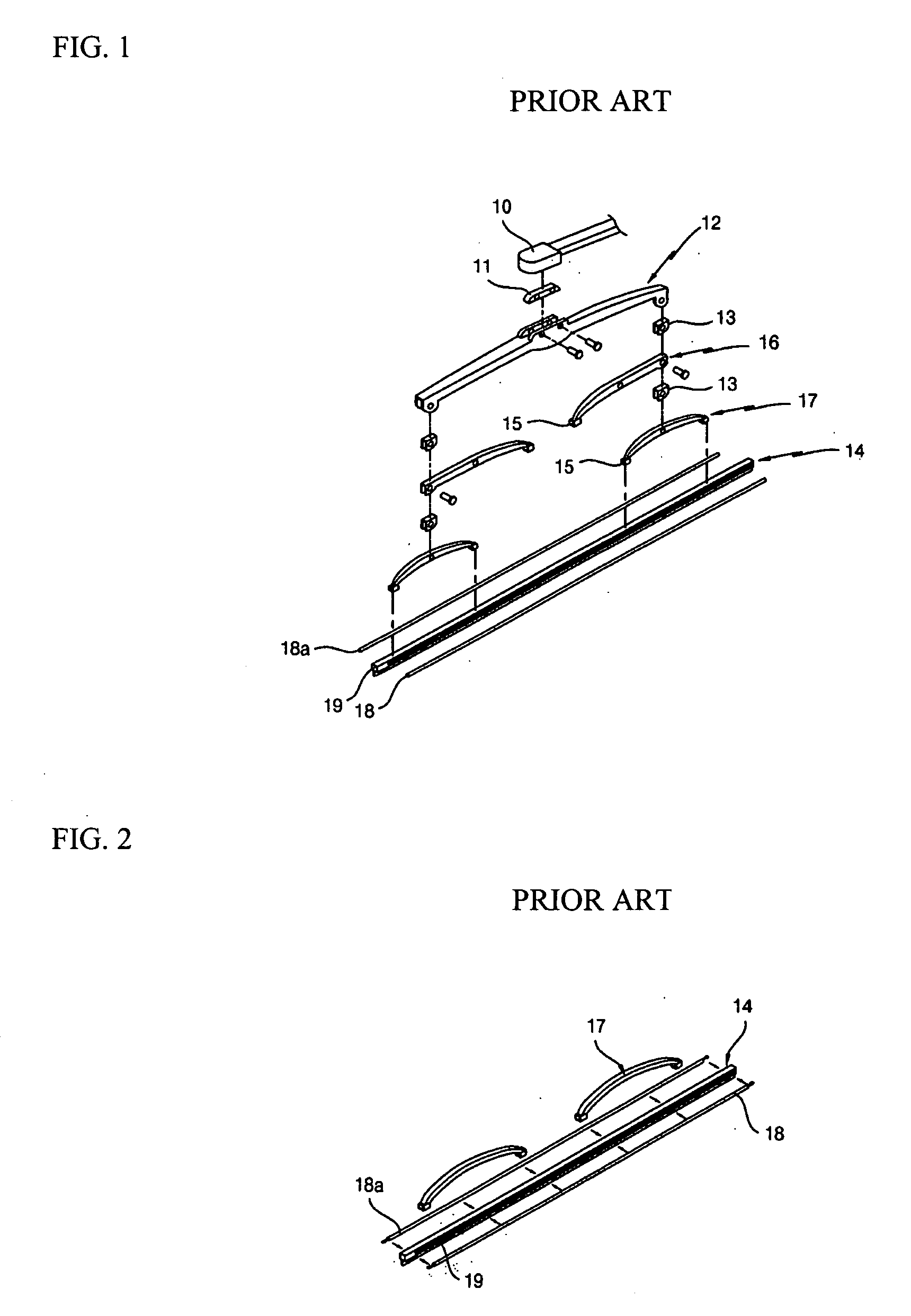
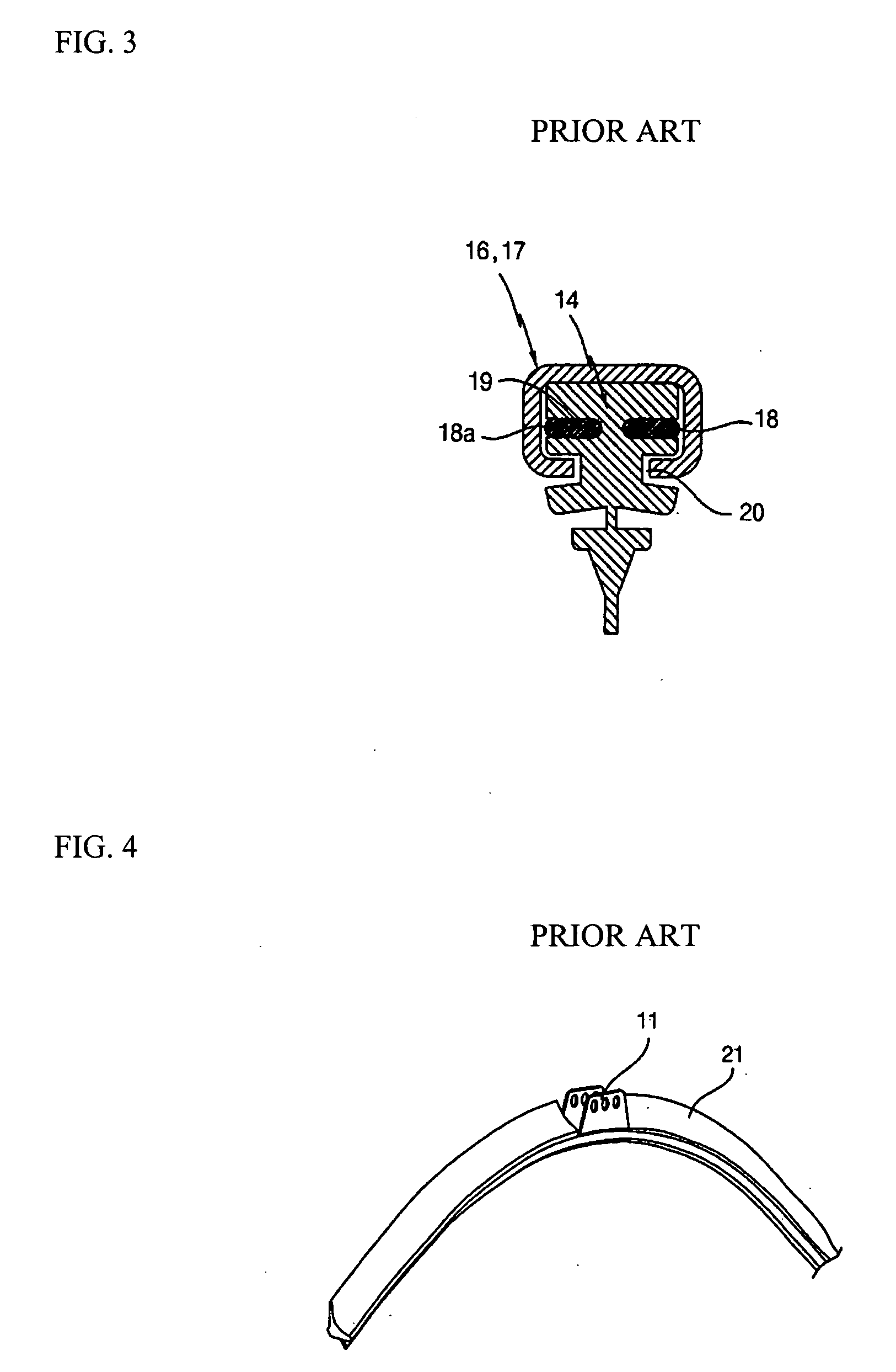
However, a problem with the foresaid wiper is that the aggregate tension of the two tension springs 18 and 18a and the rubber cover 21 necessitate the wiper arm maintaining an increased load on the wiper for the wiper to be operationally effective, unduly stressing the mechanism.
Also, this type of wiper is not interchangeable with existing wiper arms on vehicles that have a tension preset for the above-mentioned multi-point-type wiper blade.
Furthermore, as shown in FIG. 5, because the wiper requires the rubber spoiler-cum-cover to complete the formation thereof, the latter item cannot be omitted.
Therefore a separately formed spoiler is required, complicating the overall structure, and creating the possibility of vibration or judder caused by the spoiler and wind noise when pressed against a windshield.

Method used


Image

  • Rubber blade for wiper
  • Rubber blade for wiper
  • Rubber blade for wiper

Examples


Embodiment Construction

[0031] Hereinafter, preferred embodiments of the present invention will be described in detail with reference to FIGS. 7 and 8.

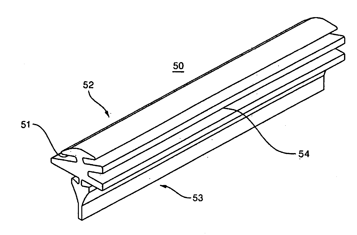
[0032]FIG. 7 is a perspective view of a rubber blade for an automotive wiper according to the present invention, and FIG. 8 is a sectional view showing the rubber blade for an automotive wiper of FIG. 7 in an assembled state.

[0033] The rubber blade for an automotive wiper shown in FIGS. 7 and 8 may be compatible with wipers using conventional rubber blades (including wipers that are formed with a tensile member having a frame integrated with a tension spring and joined with a bent adapter).

[0034] Specifically, the rubber blade of the present invention can be applied to all kinds of wipers including: a frame supporting a rubber blade pressing against a windshield surface while the frame is simultaneously connected via an adapter to a wiper arm that moves the wiper back and forth across the windshield; and a tension spring inserted along a slot on a rubber ...


PUM


Abstract

Provided is a rubber blade for an automotive wiper capable of autonomously pressing firmly and resting securely against a windshield surface by altering the structure of the rubber blade. The rubber blade has a head portion forming an upper portion of the rubber blade. The head portion includes a pair of mounting slots for mounting the rubber blade along a wiper frame. The pair of mounting slots has a sectional offset angle (θ1), dependant on the disposition of the wiper frame. A central axis in a center between the pair of mounting slots in a sectional view of the blade is offset by an angle (θ3) from a vertical axis (L1). A wiping portion forms a lower portion of the rubber blade for contacting the windshield, and is disposed in the direction of the vertical axis (L1).

Description

BACKGROUND OF THE INVENTION [0001] 1. Field of the Invention [0002] The present invention relates to a rubber blade for an automotive wiper, and more particularly, to a rubber blade for an automotive wiper that is changed in structure and shape so that it autonomously presses securely against an automotive windshield. [0003] 2. Description of the Related Art [0004] An automotive wiper is a device for wiping a vehicular windshield clear of rain and other foreign substances. A wiper motor installed inside the vehicle drives a mechanical linkage to move wiper arms back and forth in a predetermined arc. Disposed on the end of the wiper arm is a detachably mounted wiper frame to which a wiper blade made of rubber is attached. [0005] Conventional wipers attached to wiper arms include a skeletal frame and a blade portion mounted on the frame and contacting a windshield to wipe it, as shown in FIGS. 1 through 3. [0006] A conventional wiper 10 includes: a main frame 12 having an adapter 11 t...

Claims


Application Information

Patent Timeline
IPC IPC(8): B60S1/38
CPCB60S1/3808B60S2001/3836B60S1/38B60S1/32
Inventor PARK
Owner PARK LTD
Why Eureka
Eureka Blog
Learn More