Diffractive waveguide element and diffractive waveguide display

Pending Publication Date: 2020-10-22
DISPELIX OY
View PDF2 Cites 1 Cited by
  • Summary
  • Abstract
  • Description
  • Claims
  • Application Information

AI Technical Summary

Benefits of technology

[0004]It is an aim of the invention to solve the abovementioned problem and to provide s

Problems solved by technology

One problem related to diffractive waveguide eleme

Method used


Image

  • Diffractive waveguide element and diffractive waveguide display
  • Diffractive waveguide element and diffractive waveguide display
  • Diffractive waveguide element and diffractive waveguide display

Examples


Embodiment Construction

Definitions

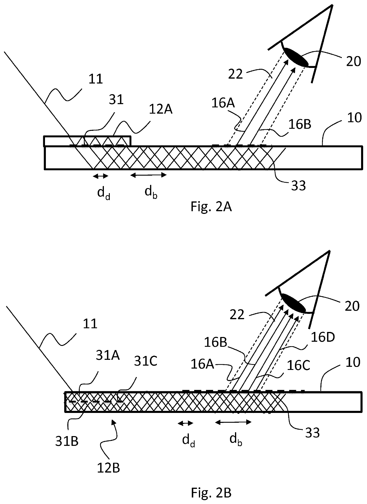
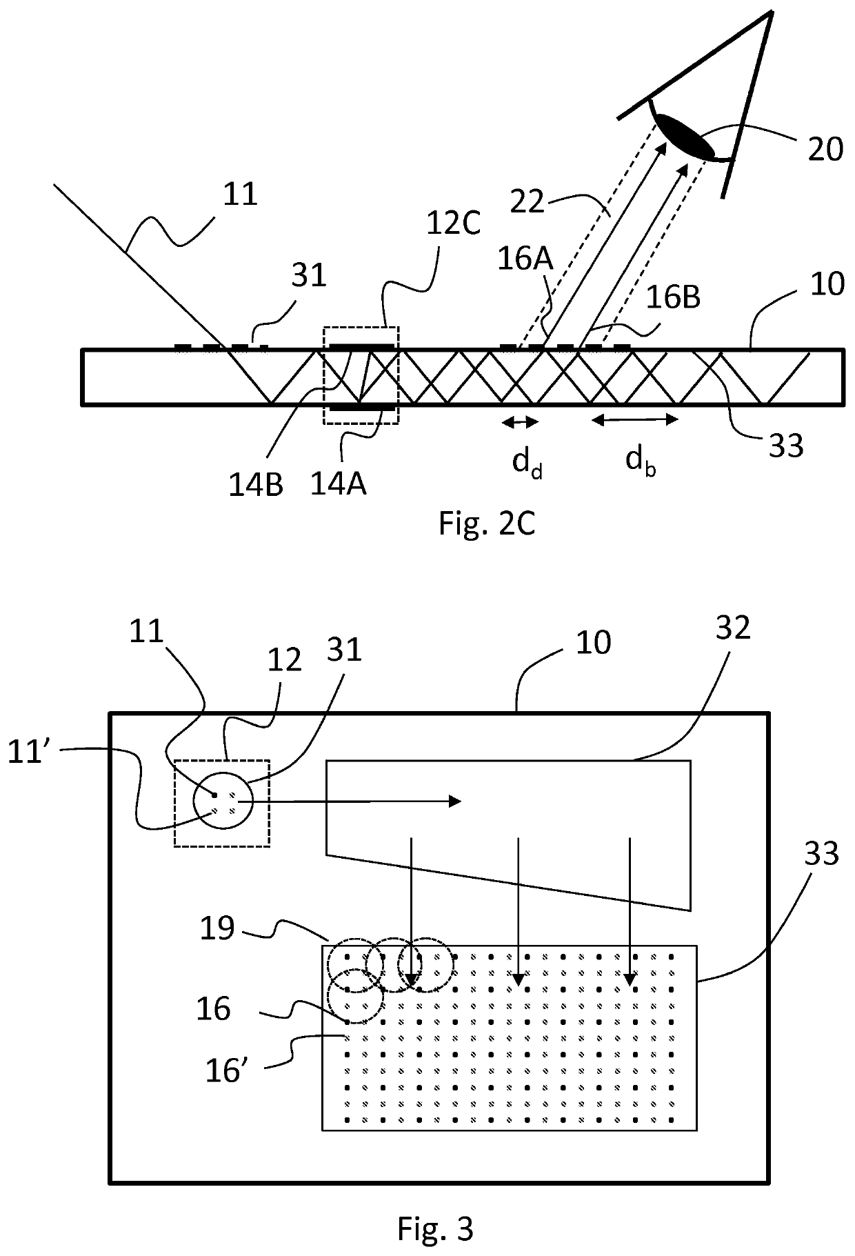
[0025]Diffractive optical element herein refers to gratings and other optical structures that contain regular or non-regular features having at least one dimension in the order of visible light wavelengths, i.e, typically less than 1 μm, and thus causes significant diffraction of light. Examples include line gratings (one dimensional gratings) and two-dimensional gratings. The gratings can be single-region gratings (with the same microstructure and optical response throughout the grating area) or multi-region gratings (i.e. containing zones having different microstructures and optical responses).

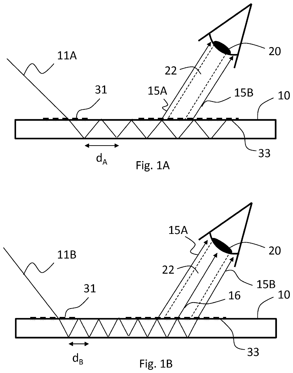
[0026]“Hop length” is the distance between two successive bouncing points of light propagating in a waveguide via total internal reflections on the same surface of the waveguide.

Description of Selected Embodiments

[0027]Beam multipliers herein discussed are needed for example when augmented reality (AR) waveguides are illuminated by laser light. For the image produced by such a wav...


PUM


Abstract

A diffractive waveguide element for a personal display device includes a display waveguide extending in a waveguide plane, an in-coupling diffractive optical element arranged onto or into the display waveguide for diffractively coupling light rays into the display waveguide, and an out-coupling diffractive optical element arranged onto or into the display waveguide for coupling the diffractively coupled light rays out of the display waveguide. In addition, there is provided a ray multiplier element optically upstream of the out-coupling diffractive optical element, the ray multiplier element being capable of splitting a light ray incoming to the in-coupling grating into a plurality of parallel rays spatially displaced in the waveguide plane before they enter the out-coupling diffractive optical element. A waveguide display device is also provided.

Description

FIELD OF THE INVENTION[0001]The invention relates to diffractive waveguides. Such waveguides can be used in personal display devices, such as head-mounted displays (HMDs) and head-up displays (HUDs).BACKGROUND OF THE INVENTION[0002]Waveguides are key image-forming elements in many modern personal display devices. The image to be displayed can be coupled into and out of the waveguide, as well as modified within the waveguide, using diffractive gratings. For example, there may be provided an in-coupling grating for coupling an image from a projector into the waveguide, an exit pupil expander grating for expanding the light field in one or more in-plane dimensions of the waveguide, and an out-coupling grating which couples the image of the waveguide to the user's eye.[0003]One problem related to diffractive waveguide elements is striping of the image out-coupled therefrom. This is because the light beams travelling in the waveguide via total internal reflections may have a bouncing per...

Claims


Application Information

Patent Timeline
IPC IPC(8): G02B27/42G02B27/00G02B27/01F21V8/00G02B5/18
CPCG02B6/0016G02B5/1828G02B27/0172G02B27/4272G02B27/0081G02B27/0101G02B6/0043G02B6/0028G02B27/01G02B27/00G02B27/017G02B5/00G02B6/00G02B5/1814G02B27/0103G02B6/10
Inventor BLOMSTEDT, KASIMIROLKKONEN, JUUSOSUNNARI, ANTTI
Owner DISPELIX OY
Why Eureka
Try Eureka