Polishing mechanism used for shaft

A technique for polishing mechanisms and shafts, which is applied in the direction of grinding/polishing equipment, grinding workpiece supports, grinding machines, etc. It can solve problems such as uneven polishing and abrasive belt polishing marks, and achieve strip-shaped grinding marks, uniform grinding, and Better polishing effect

Active Publication Date: 2017-06-13
重庆普莱斯恩机械制造有限公司
View PDF9 Cites 2 Cited by
  • Summary
  • Abstract
  • Description
  • Claims
  • Application Information

AI Technical Summary

Problems solved by technology

[0004] The purpose of the present invention is to provide a shaft polishing mechanism to solve the problems that

Method used


Image

  • Polishing mechanism used for shaft
  • Polishing mechanism used for shaft

Examples


Embodiment Construction

[0015] The present invention will be described in further detail below by means of specific embodiments:

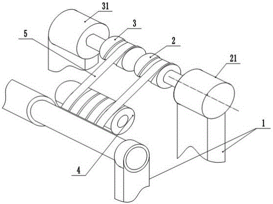
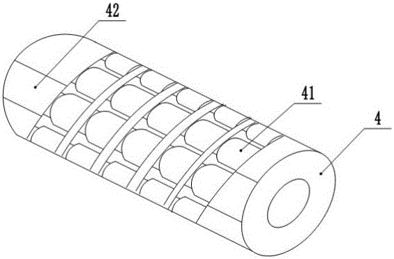
[0016] The reference signs in the drawings of the description include: frame 1, first driving roller 2, first motor 21, second driving roller 3, second motor 31, driving roller 4, roller 41, end plane 42, abrasive belt 5 .

[0017] The embodiment is basically as attached figure 1 And attached figure 2 Shown:

[0018] A polishing mechanism for a shaft, mainly composed of a clamping device, a frame 1, an abrasive belt 5, a driving roller 4, a first driving roller 2 and a second driving roller 3, the clamping device and the driving roller are installed on the frame 1 Above, the clamping device is composed of a three-jaw chuck for clamping the shaft parts and a support plate for clamping the end of the shaft parts, and the support plate is rotatably connected to the frame 1 . The transmission roller 4 is fixedly connected on the frame 1, and the transmission roller 4 is ...


PUM


Abstract

The invention belongs to the field of machine tools for grinding or polishing and specifically discloses a polishing mechanism used for a shaft. The polishing mechanism comprises a clamping device, a rack, abrasive belts, a transmission roller, a first drive roller and a second drive roller. The transmission roller is fixedly connected to the rack, the transmission roller is provided with a spiral strip-shaped slot along the roller surface, and the strip-shaped slot is internally provided with a plurality of rollers which are uniformly distributed along the spiral track; and the abrasive belts are arranged along the spiral strip-shaped slot in the transmission roller and matched with the rollers, one end, stretching out of the transmission roller, of each abrasive belt is wound on the first drive roller, and the other end of the corresponding abrasive belt is wound on the second drive roller. According to the polishing mechanism used for the shaft, through specific structures of the spiral strip-shaped slot in the transmission roller and the rollers, inclined arrangement and continuous transmission of the abrasive belts are achieved, through inclined polishing of the abrasive belts, strip-shaped polishing scratches are avoided, polishing is more uniform, and the polishing effect is better; and through intermittent reverse polishing, oneness of polishing textures on the surface of the shaft is avoided, and polishing is more uniform.

Description

technical field [0001] The invention relates to the field of machine tools for grinding or polishing. Background technique [0002] The grinding of the shaft follows the process of rough grinding first, then fine grinding and polishing. Coarse grinding generally uses emery wheels of different particle sizes. If higher particle size grinding is required, precision polishing abrasive belts are often used for polishing. That is, the processed shaft is fixed by the supporting plate, and the workpiece is driven to rotate by the circular motion of the guide wheel towards the supporting plate, and the surface of the shaft is ground by the abrasive belt rotating in the opposite direction. Since the grain size of the abrasive belt is higher than that of the grinding wheel, it is When cutting the shaft, the surface quality is high, and the precision is relatively high. [0003] However, due to the limited width of the existing polishing abrasive belt, it can only process the surface...

Claims


Application Information

Patent Timeline
IPC IPC(8): B24B21/02B24B21/18B24B41/06
CPCB24B21/025B24B21/18B24B41/06
Inventor 罗贵良
Owner 重庆普莱斯恩机械制造有限公司
Why Eureka
Try Eureka