Developing apparatus, cartridge and image forming apparatus

Active Publication Date: 2005-08-18
CANON KK
View PDF10 Cites 2 Cited by
  • Summary
  • Abstract
  • Description
  • Claims
  • Application Information

AI Technical Summary

Benefits of technology

[0023] It is an object of the present invention to provide a developing apparatus, a cartridge and an image forming apparatus in

Problems solved by technology

However, if the user rotates the developing sleeve by mistake with the toner seal 50 remaining provided, when the developing blade is formed of an elastic material such as urethane rubber, there are the problems that the developing blade is turned up in the direction of rotation of the developing sleeve due to the frictional resistance between the developing blade and the developing sleeve, and it becomes impossible to effect uniform and good toner coating, and the problems that deep friction

Method used


Image

  • Developing apparatus, cartridge and image forming apparatus
  • Developing apparatus, cartridge and image forming apparatus
  • Developing apparatus, cartridge and image forming apparatus

Examples


Example

[0044] A first embodiment of the present invention will hereinafter be described with reference to the accompanying drawings.

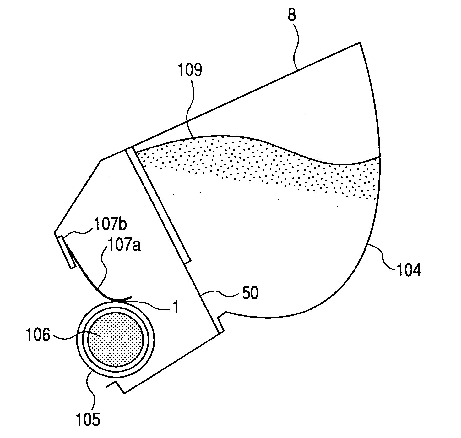
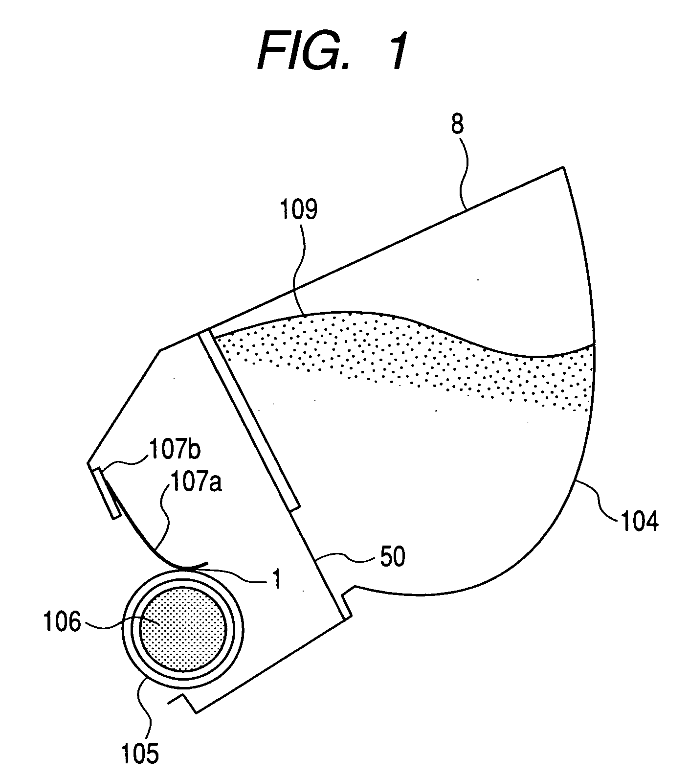
[0045]FIG. 1 shows the feature of a developing apparatus 8 according to the first embodiment of the present invention best.

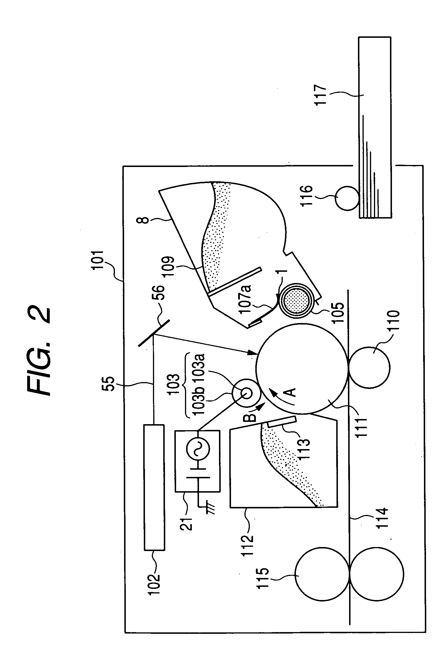
[0046]FIG. 2 shows a state in which the developing apparatus 8 according to the first embodiment of the present invention is installed in the main body of an image forming apparatus after the toner seal 50 of the developing apparatus has been removed. The same constituents as those described in the conventional art are given the same reference characters. When the developing apparatus is in a new state, a removable toner seal 50 is provided, as shown in FIG. 12, so that a toner as a developer may not adhere to a developing sleeve 105 which is a developer carrying member and a developing blade 107a which is a developer regulating member. When a user begins to use the developing apparatus, the user removes the toner seal 50, whereby it bec...

Example

Second Embodiment

[0062] A feature of this embodiment is that the photosensitive drum which is an image bearing member, the charging roller which is charging means (charging member) and the developing apparatus are provided together in an interchangeable integral type cartridge, which in turn is detachably provided in the main body of the image forming apparatus. The charging roller need not always be provided in the cartridge, and the charging roller and the photosensitive drum can be provided not in the cartridge, but in the main body of the image forming apparatus, or the charging roller and the photosensitive drum may be detachably mountable on the main body of the image forming apparatus as a cartridge discrete from the cartridge provided with the developing apparatus.

[0063]FIG. 4 shows an example of the integral type cartridge, and FIG. 5 shows a state in which after the toner seal 50 has been removed in the integral type cartridge 6, the cartridge has been inserted into the ...

Example

Third Embodiment

[0066] A feature of this embodiment shows, for example, the case of an image forming apparatus of such a cleanerless system as proposed in Japanese Patent Application Laid-open No. H10-307455.

[0067]FIG. 6 shows the feature of an image forming apparatus according to a third embodiment of the present invention best. In FIG. 6, the same constituents as those described in the example of the conventional art are given the same reference characters.

[0068] The main body 300 of the image forming apparatus in FIG. 6 uses a direct injection charging process. The direct injection charging process is a process in which charges are directly injected from a contact charging member into a member to be charged (here, the photosensitive drum) through a portion of contact, whereby the surface of the member to be charged is charged. It is also called direct charging, or injection charging, or charge injection charging. More particularly, it effects charge injection directly into the...


PUM


Abstract

A developing apparatus having a developer carrying member for carrying a developer thereon and developing an electrostatic image formed on an image bearing member with a developer, a developer layer thickness regulating member provided in contact with the developer carrying member for regulating the thickness of the layer of the developer carried on the developer carrying member, and an electrically conductive particle provided in the portion of contact between the developer carrying member and the developer layer thickness regulating member, in a state in which the developer does not exist between the developer carrying member and the developer layer thickness regulating member.

Description

BACKGROUND OF THE INVENTION [0001] 1. Field of the Invention [0002] The invention relates to an image forming apparatus, a cartridge and a developing apparatus for application to an electrophotographic apparatus such as a laser beam printer or a copying machine and an electrostatic recording apparatus or the like. [0003] 2. Description of the Related Art [0004]FIG. 9 of the accompanying drawings shows an image forming apparatus as an example using a conventional developing apparatus. In FIG. 9, the reference numeral 101 designates the main body of the image forming apparatus which is a printer engine. The reference numeral 111 denotes a cylindrical photosensitive drum which is an image bearing member, and it is rotated in one direction about the axis thereof. A charging roller 103 is constituted by a mandrel 103a and a rubber material 103b disposed on the mandrel 103a, and uniformly charges the surface of the photosensitive drum 111. [0005] After the surface of the photosensitive dr...

Claims


Application Information

Patent Timeline
IPC IPC(8): G03G15/08G03G15/00G03G15/06G03G21/16
CPCG03G15/0812G03G15/0808G03G15/081G03G15/0856G03G15/0921G03G21/1814
Inventor YOSHIDA, MASAHIRO
Owner CANON KK
Why Eureka
Try Eureka