A molding device for optical glass and its production process

An optical glass and molding device technology, which is applied to the production of lanthanide optical glass strips with a molding thickness of more than 40mm, and the field of optical glass strip molding devices, can solve the problem that the overall quality is not improved, the glass molding quality is not improved, Increase the surface viscosity of the glass liquid and other problems to achieve the effects of accurate and stable molding temperature control, avoiding surface streaks and crystallization, and improving stability

Active Publication Date: 2016-04-20
HUBEI NEW HUAGUANG NEW INFORMATION MATERIALS CO LTD
View PDF2 Cites 2 Cited by
  • Summary
  • Abstract
  • Description
  • Claims
  • Application Information

AI Technical Summary

Problems solved by technology

However, the molding quality of the glass is not improved, and the surface viscosity of the glass liquid is increased during the cooling process, which makes the glass molding R angle larger
[0006] The above two patents respectively improved the R angle and facial stripes of optical glass strips during the molding process by heating or cooling the mold surface, but they were only one-sided improvements, and each invention could only solve both facial stripes and R angles. One of the molding problems, the overall quality of the glass after molding has not improved

Method used


Image

  • A molding device for optical glass and its production process
  • A molding device for optical glass and its production process
  • A molding device for optical glass and its production process

Examples


Embodiment Construction

[0039] The present invention will be further described below in conjunction with the accompanying drawings.

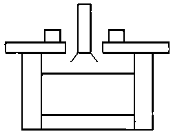
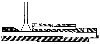
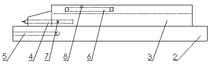
[0040] Such as image 3 , Figure 4 , Figure 7 shown. The optical glass forming device of the present invention includes a bottom mold 2 , a top mold 3 , a heating device 4 , a bottom mold cooling channel 5 , a top mold cooling channel 6 , a first temperature measuring thermocouple 7 and a second temperature measuring thermocouple 8 . Top mold 3 is 20-40mm thick, 300-600mm long U-shaped groove, bottom mold 2 is 30-80mm thick, 500-800mm long flat bottom plate, top mold 3 and bottom mold 2 are installed together to form glass molding cavity. The groove width (mold cavity width) of the U-shaped groove is 100-200mm, and the groove height is 40-80mm, which can produce optical glass strips of various diameters corresponding to the cavity size. The front end of the top mold 3 cuts out a 50-100mm long slope, which is convenient for the installation of the leakage pipe and t...


PUM

PropertyMeasurementUnit
widthaaaaaaaaaa
lengthaaaaaaaaaa

Abstract

The present invention relates to a forming device of optical glass and its production technology, which belong to the technical field of optical glass melting. The forming device of optical glass and its production technology solve the problems of poor forming quality, easy generation of surface stripe and crystallization of a strip material of the optical glass with large aperture, the forming device comprises a bottom die, a top die, a heating device, a bottom die cooling channel, a top die cooling channel, a first temperature thermocouple and a second temperature thermocouple; the top die is in an U-shaped groove, the bottom die is a plane base plate, the top die and the bottom die are arranged together to form a glass forming cavity; the top die cooling channel and the second temperature thermocouple are arranged on the upper wall of the top die; the bottom die cooling channel is arranged in the plate of the bottom die; and the heating device and the first temperature thermocouple are arranged in the U-shaped groove at the lower part of the top die. The forming device solves the problems that the forming of the strip material of the optical glass is poor, the thickness is inconsistent, surface stripe and crystallization are easily generated, and has obvious effect for lanthanide optical glass with low viscosity and easy crystallization.

Description

technical field [0001] The invention belongs to the technical field of optical glass fusion molding. Specifically relates to a forming device for optical glass strips and a production method thereof, in particular to a forming device and a production method for producing lanthanide optical glass strips with a thickness exceeding 40mm. Background technique [0002] In the field of optical glass melting and forming, the strip forming process is a main forming process. In the molten state, the optical glass is naturally formed or pressed by a mold and cut into optical glass strips of a certain size. The glass strip forming device is generally composed of a bottom mold, a side mold and a plug. Because the glass liquid has the characteristic of rapid solidification as the temperature decreases, the optical glass strips produced in this way have relatively large rounded corners (referred to as R corners), such as Figure 5 shown. The R angle is generated at the forming edge of t...

Claims


Application Information

Patent Timeline
Patent Type & Authority Patents(China)
IPC IPC(8): C03B11/06
Inventor 张泰山周希光冦小勇
Owner HUBEI NEW HUAGUANG NEW INFORMATION MATERIALS CO LTD
Why Eureka
Try Eureka