Injection molding apparatus and injection molding method

a technology of injection molding and injection molding apparatus, which is applied in the field of injection molding of resins, can solve the problems that the obtained fiber reinforced resin molded article may not be able to satisfy a desired property, and achieve the effects of preventing the generation of a region, small reinforcing fiber content, and small amount of fiber

Active Publication Date: 2016-01-14
U MHI PLATECH CO LTD +1
View PDF3 Cites 22 Cited by
  • Summary
  • Abstract
  • Description
  • Claims
  • Application Information

AI Technical Summary

Benefits of technology

[0024]In accordance with the present invention, by increasing the lead L2 of the second flight, the reinforcing fibers fed in the injecting process or the plasticizing process are easily charged into the screw groove, so that a region of the screw groove with a small reinforcing fiber amount can be reduced. Therefore, in accordance with the present invention, it is possible to prevent generation of a region with a small reinforcing fiber content in a molded article. It is also possible to thereby obtain a stable molding quality.

Problems solved by technology

Thus, a fiber length after molding becomes significantly shorter than an original fiber length, and the obtained fiber reinforced resin molded article may not be able to satisfy a desired property (Patent Literature 1).

Method used


Image

  • Injection molding apparatus and injection molding method
  • Injection molding apparatus and injection molding method
  • Injection molding apparatus and injection molding method

Examples


first embodiment

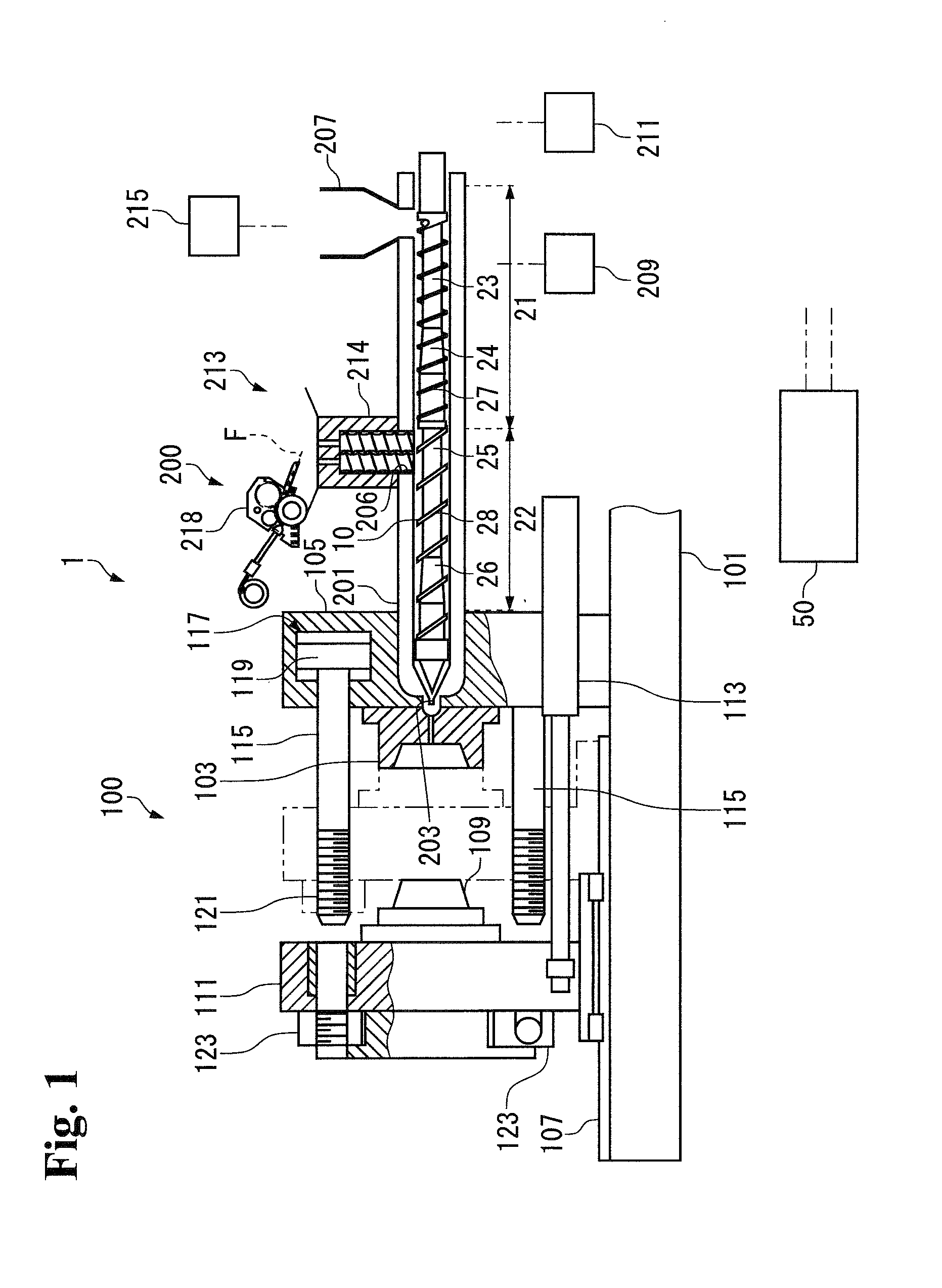
[0032]An injection molding machine 1 according to a present embodiment includes a mold clamping unit 100, a plasticizing unit 200, and a control section 50 that controls operations of the units as shown in FIG. 1.

[0033]In the following, outlines of a configuration and the operation of the mold clamping unit 100, and a configuration and the operation of the plasticizing unit 200 are described, and a procedure of injection molding by the injection molding machine 1 is subsequently described.

[Configuration of the Mold Clamping Unit]

[0034]The mold clamping unit 100 includes a fixed die plate 105 that is fixed onto a base frame 101, and to which a fixed mold 103 is attached, a movable die plate 111 that moves in a right-left direction in the drawing on a slide member 107, such as a rail and a slide plate, by operating a hydraulic cylinder 113, and to which a movable mold 109 is attached, and a plurality of tie bars 115 that connect the fixed die plate 105 and the movable die plate 111. I...

second embodiment

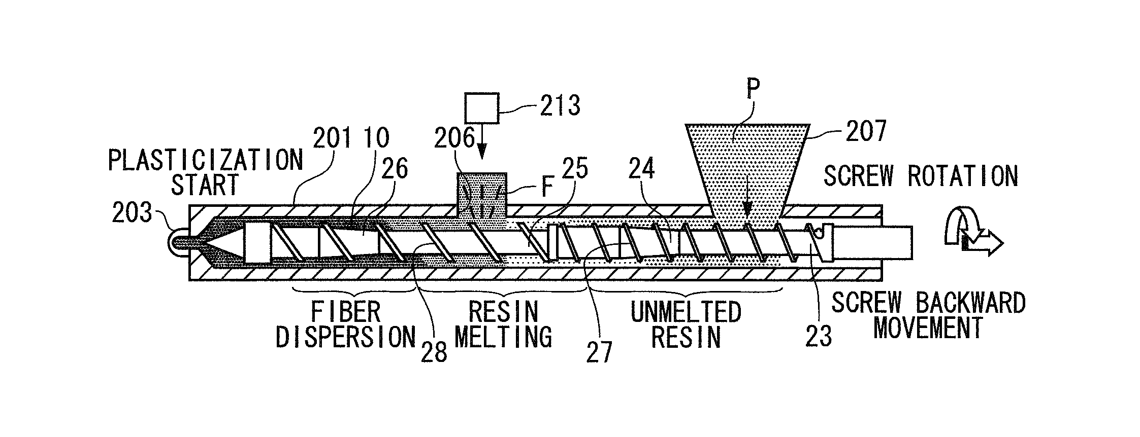
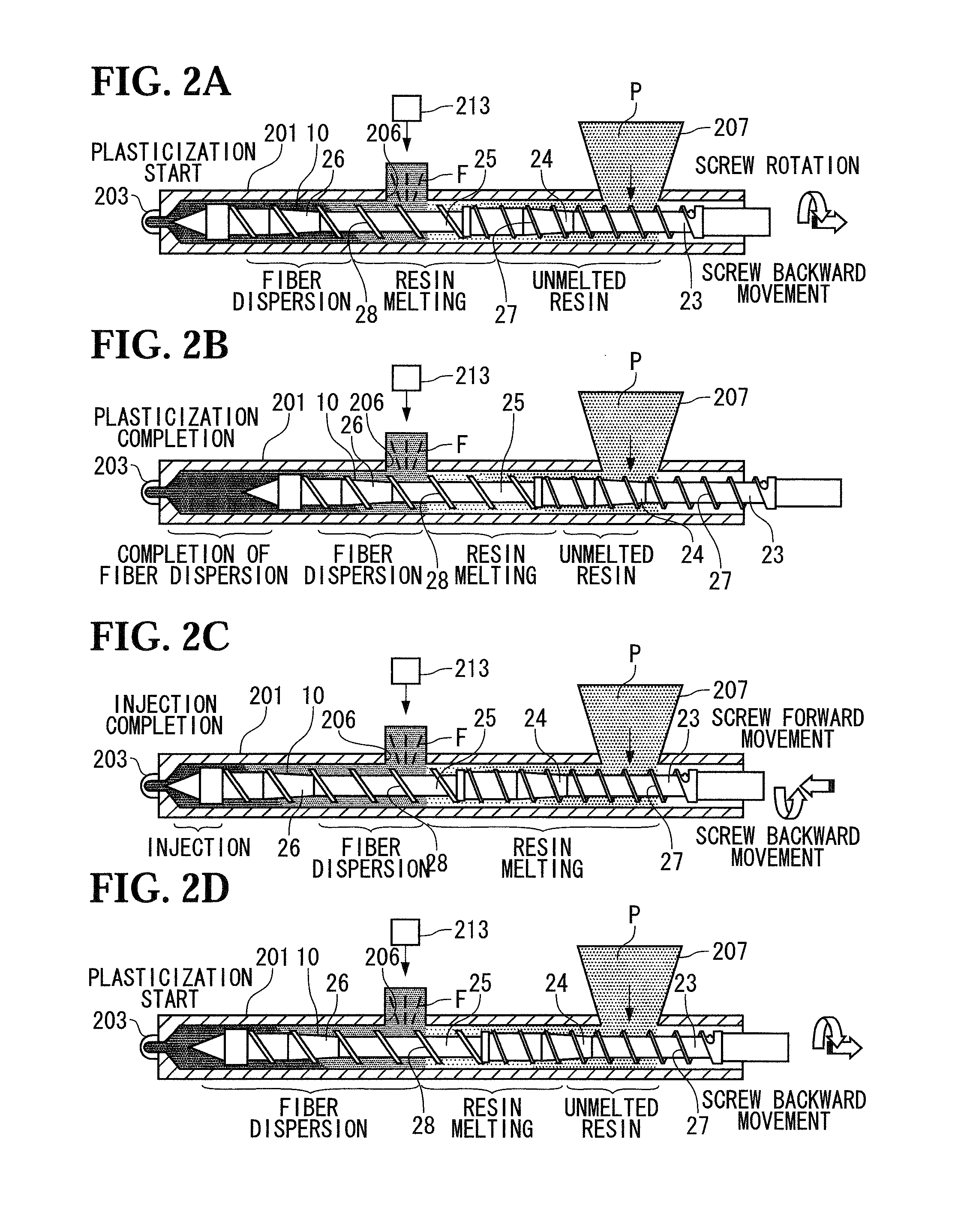
[0097]In a present embodiment, the screw 10 is reversely rotated during the injecting process in order to more smoothly feed the reinforcing fibers F by using the injection molding machine 1 of the first embodiment. In the following, a point different from the first embodiment is mainly described.

[0098]Conventionally, the rotation of the screw 10 is stopped during the injecting process. In this case, however, the reinforcing fibers F may not be smoothly fed. That is, even by using the fiber feed device 213 described in the first embodiment, if a feed force of the fiber feed device 213 is small or the like, the reinforcing fibers F cannot overcome resin resistance in the groove of the screw 10, and cannot be charged into the lower side of the screw 10 during the injecting process.

[0099]In contrast, in accordance with the present embodiment in which the screw 10 is reversely rotated during the injecting process, the reinforcing fibers F sticking to the melted resin M are also conveyed...


PUM

PropertyMeasurementUnit
lengthaaaaaaaaaa
lengthaaaaaaaaaa
pressureaaaaaaaaaa

Abstract

The injection molding apparatus of the present invention includes: a heating cylinder; a screw that is provided rotatably in an inner portion of the heating cylinder; a resin feed hopper that feeds a resin pellet; and a fiber feed device that is provided ahead of the resin feed hopper and feeds reinforcing fibers into the heating cylinder. The screw includes a first stage that is located on a rear side, and in which the resin pellet is melted, and a second stage that is located on a front side, and in which the melted resin pellet and the reinforcing fibers are mixed, and a lead of a second flight provided in the second stage is larger than a lead of a first flight provided in the first stage.

Description

TECHNICAL FIELD[0001]The present invention relates to injection molding of a resin containing reinforcing fibers.BACKGROUND ART[0002]Molded articles of a fiber reinforced resin whose strength is increased by containing reinforcing fibers are used for various purposes. To obtain the molded articles by injection molding, a thermoplastic resin is melted by rotating a screw in a cylinder that is a plasticizing device, kneaded with fibers, and then injected into a mold of an injection molding apparatus.[0003]In order to obtain the effect of improving strength by the reinforcing fibers, the reinforcing fibers are desired to be dispersed uniformly in the resin. Although a strict kneading condition may be employed for achieving the uniform dispersion, a shear force on a kneaded material is inversely increased, and the reinforcing fibers are thereby cut off. Thus, a fiber length after molding becomes significantly shorter than an original fiber length, and the obtained fiber reinforced resin...

Claims


Application Information

Patent Timeline
Patent Type & Authority Applications(United States)
IPC IPC(8): B29C45/18B29C45/00B29C45/50B29C45/60
CPCB29C45/60B29K2105/12B29C45/50B29C45/1808B29C45/0005B29C45/1816B29C45/18B29B7/248B29B7/429B29B7/72B29B7/826B29B7/845B29B7/905
Inventor KARIYA, TOSHIHIKOTODA, NAOKINOBUTA, MUNEHIROKINOSHITA, KIYOSHIYAMAGUCHI, TAKESHIIKEDA, KOSUKESUZUMURA, YUJIONUMA, HITOSHIOKABE, RYOJITAKAHASHI, MASANORI
Owner U MHI PLATECH CO LTD
Why Eureka
Try Eureka