Nozzle and method for washing gas turbine compressors

a gas turbine and compressor technology, applied in the direction of electrostatic cleaning, hollow article cleaning, lighting and heating apparatus, etc., can solve the problems of reducing the aerodynamic properties, reducing the pressure gain, and gas turbines in operation consume large quantities of air, so as to achieve efficient and safe methods

Active Publication Date: 2007-01-04
GAS TURBINE EFFICIENCY
View PDF14 Cites 63 Cited by
  • Summary
  • Abstract
  • Description
  • Claims
  • Application Information

AI Technical Summary

Benefits of technology

[0014] One objective with the invention is to provide a nozzle and a method for washing of a gas turbine during operation in an efficient and safe way.

Problems solved by technology

Gas turbines in operation consumes large quantities of air.
However, there are particles with the properties of sticking on to components in the engine's gas path.
These particles build up a coating on the components, reducing the aerodynamic properties.
The coating result, in an increase in the surface roughness which result in a decrease in the pressure gain as well as a reduction of the air flow that the compressor compresses.
For the gas turbine unit it results in a decrease in efficiency, a reduced mass flow and a reduced pressure ratio.
These filters can only capture a portion of the particles.
The disadvantage with the method is that nut shell material may find its way into the internal air system of the gas turbine with the consequence of clogging of channels and valves.
With these large geometries there may be difficulties in injecting washing fluid into the part of the duct with the core air stream.
If the liquid on the contrary will follow close to the duct wall, the liquid will in an unsatisfactory way wet the blades and vanes.
This liquid will not participate in washing of the compressor and can cause damage of, for example, the liquid fills the gap between the rotor tip and compressor casing.
One problem is that conventional nozzles can not penetrate the air stream of large gas turbines.
While practising this method the gas turbine must be taken out of service which may cause production loss and costs.
This method is not as efficient as the crank wash method.
The lower efficiency relates to poor washing mechanisms prevailing at high rotor speeds when the gas turbine is in operation.
For example, a correct dose of liquid must be injected as a too high dose may cause mechanical damage to the compressor and a too low dose may cause poor wetting of the compressor components.
Further, the droplets must be small else large droplets may cause erosion damage from the collision of the droplets with the rotor and stator blades.
The disadvantage with small droplets is that have a small mass and thereby low inertia when leaving the nozzle.
The droplets velocity is quickly reduced by the air resistance and the range is therefore limited.
The disadvantage with the larger droplet is that when the droplets are caught by the air stream they also achieve high velocity towards the compressor.
The damages will appear as erosion damages.
A difficulty with the on-line wash method, e.g. as shown in U.S. Pat. No. 5,011,540 is to get the liquid into the core of the air duct.
As previously mentioned there are very high velocities in the air duct which drags the wash liquid before it has penetrated into the core of the air stream.
However, small droplets show a disadvantage in this respect.
A spray of small droplets has therefore an impaired ability to penetrate into the core of the air stream.
This problem is especially evident for large gas turbines with large air duct geometries where the distance from the nozzle to the centre of the air duct is long.
In summary, the washing of gas turbines, especially during gas turbine operation, is associated with a number of problems.

Method used


Image

  • Nozzle and method for washing gas turbine compressors
  • Nozzle and method for washing gas turbine compressors
  • Nozzle and method for washing gas turbine compressors

Examples


Embodiment Construction

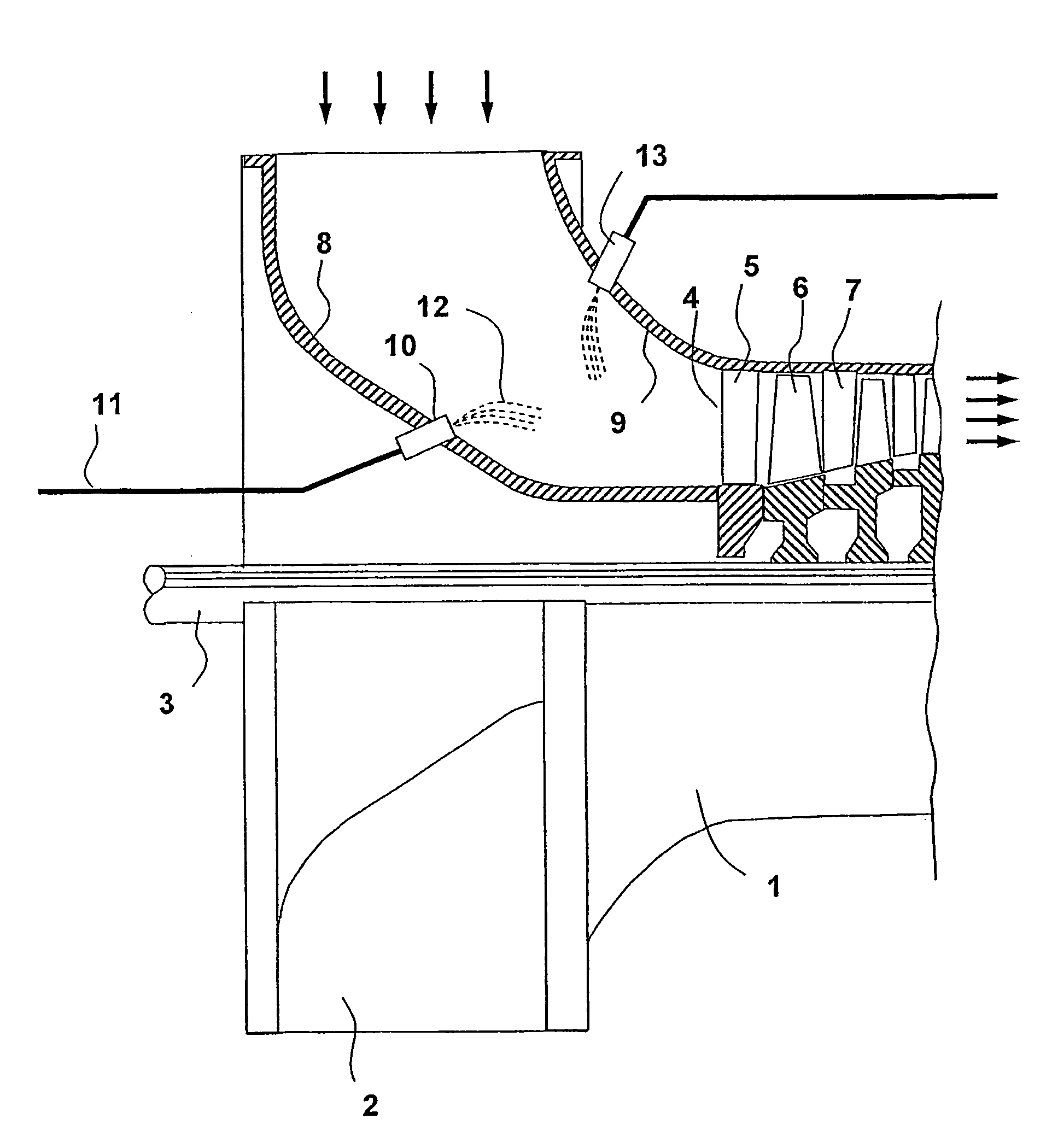
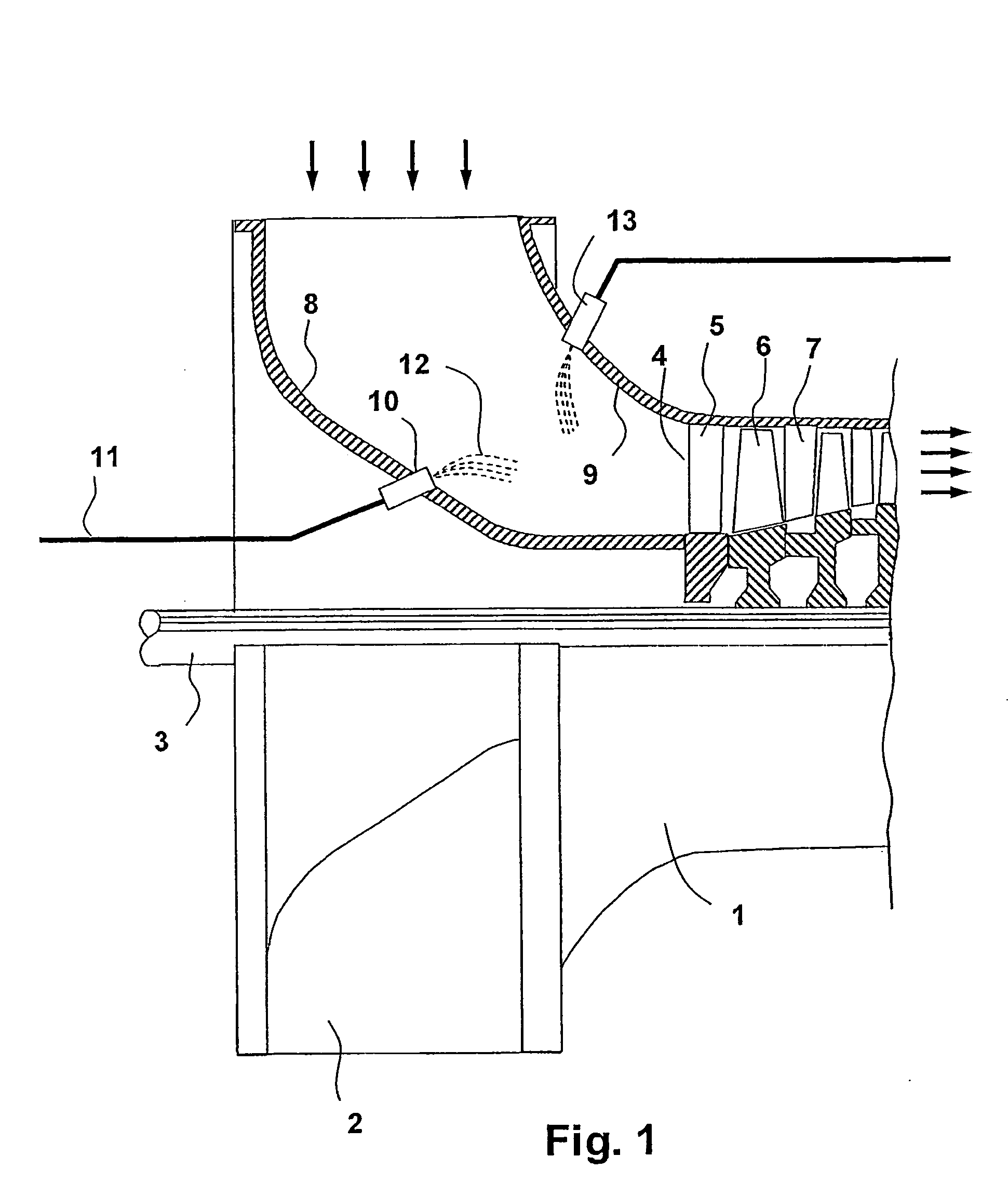
[0040] With reference to FIG. 1, a section of a gas turbine 1 and the positioning of nozzles for injecting of wash liquid into a compressor inlet are shown. The gas turbine comprises of an air intake 2 which is rotationally symmetric to axis 3. The air flow is indicated by arrows. Air enters radially to be rerouted and flow parallel to the machine shaft through compressor 14. Compressor 14 has an inlet 4 at the leading edge of the first disc of stator vanes. After disc 5 with stator vanes follows a disc 6 with rotor blades, followed by a disk 7 with stator vanes, and so on. The air intake has an inner duct wall 8 and an outer duct wall 9. A nozzle 10 is installed on the inner duct wall. A conduit 11 connects the nozzle with a pump (not shown) which supplies the nozzle with wash fluid. After passing nozzle 10 the liquid atomizes and forms a spray 12. The droplets are carried with the air stream to compressor inlet 4. Alternatively, nozzle 13 is installed on the outer air duct wall 9....


PUM


Abstract

A nozzle (54) for cleaning a gas turbine unit (1) during operation. The invention further relates to a method for washing a gas turbine unit (1) during operation. The nozzle (54) is arranged to atomize a wash liquid in the air stream in an air intake (2) of the gas turbine unit (1) and comprises a nozzle body (40) comprising an intake end (41) for intake of said wash liquid and outlet end (55) for exit of said wash liquid. The nozzle further comprises a number of orifices (42, 46; 42, 46, 60) that are connected to the outlet end (55) and respective orifice (42, 46; 42, 46, 60) is arranged at a suitable distance from a centre axis (49) of said nozzle body (40), whereby the local density of the injected wash liquid in a desired area can be increased with preserved droplet size and thereby the efficiency of the cleaning process can be significantly improved at the same time as the risk for damaging the components in the gas turbine unit is significantly reduced.

Description

TECHNICAL FIELD [0001] This invention relates to washing of gas turbines and particularly to a nozzle for washing a gas turbine unit during operation. Further the invention relates to a method for washing of said gas turbine unit under operation. DESCRIPTION OF PRIOR ART [0002] The invention relates to the general art of washing gas turbine equipped with axial compressors or radial compressors. Gas turbines comprise of a compressor for compressing air, a combustor for combusting fuel together with the compressed air and a turbine driving the compressor. The compressor comprises in turn multiple compression stages, where a compression stage comprises of a rotor disc and subsequent stator disc with vanes. [0003] Gas turbines in operation consumes large quantities of air. The air contains contaminants in form of small particles, called aerosols, that enters the compressor with the air stream. A majority of these particles will follow the air stream and exit the gas turbine with the exh...

Claims


Application Information

Patent Timeline
Patent Type & Authority Applications(United States)
IPC IPC(8): B08B3/02F01D25/00
CPCB08B3/02F01D25/002B08B9/00F04D29/705
Inventor ASPLUND, PETERHJERPE, CARL-JOHAN
Owner GAS TURBINE EFFICIENCY
Why Eureka
Try Eureka