
Reduced-weight run flat assembly comprising a pressure-effect structural support

Inactive Publication Date: 2007-01-04
MICHELIN RECH & TECH SA
View PDF1 Cites 0 Cited by
  • Summary
  • Abstract
  • Description
  • Claims
  • Application Information

AI Technical Summary

Benefits of technology

[0011] The difference in pressure between the two volumes results in a force directed radially towards the inside and acting on the support and having the effect of flattening said support on the rim. This force opposes the centrifugal force and assists in holding the support in p

Problems solved by technology

The use of reinforcement plies is a factor which contributes to an increase in the ma

Method used


Image

  • Reduced-weight run flat assembly comprising a pressure-effect structural support
  • Reduced-weight run flat assembly comprising a pressure-effect structural support
  • Reduced-weight run flat assembly comprising a pressure-effect structural support

Examples


Example

DETAILED DESCRIPTION OF THE DRAWINGS

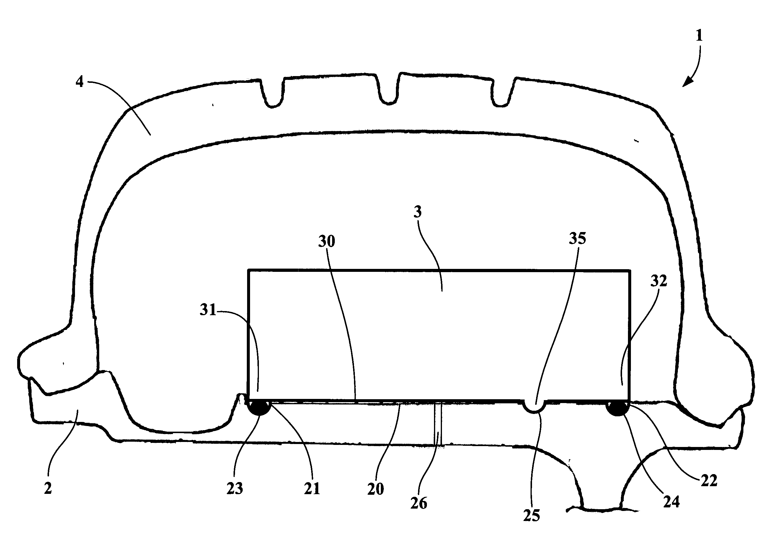
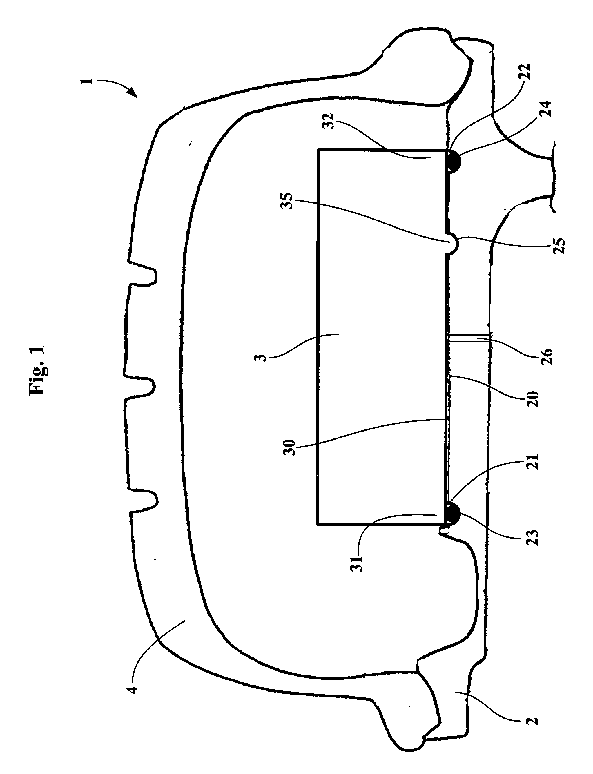
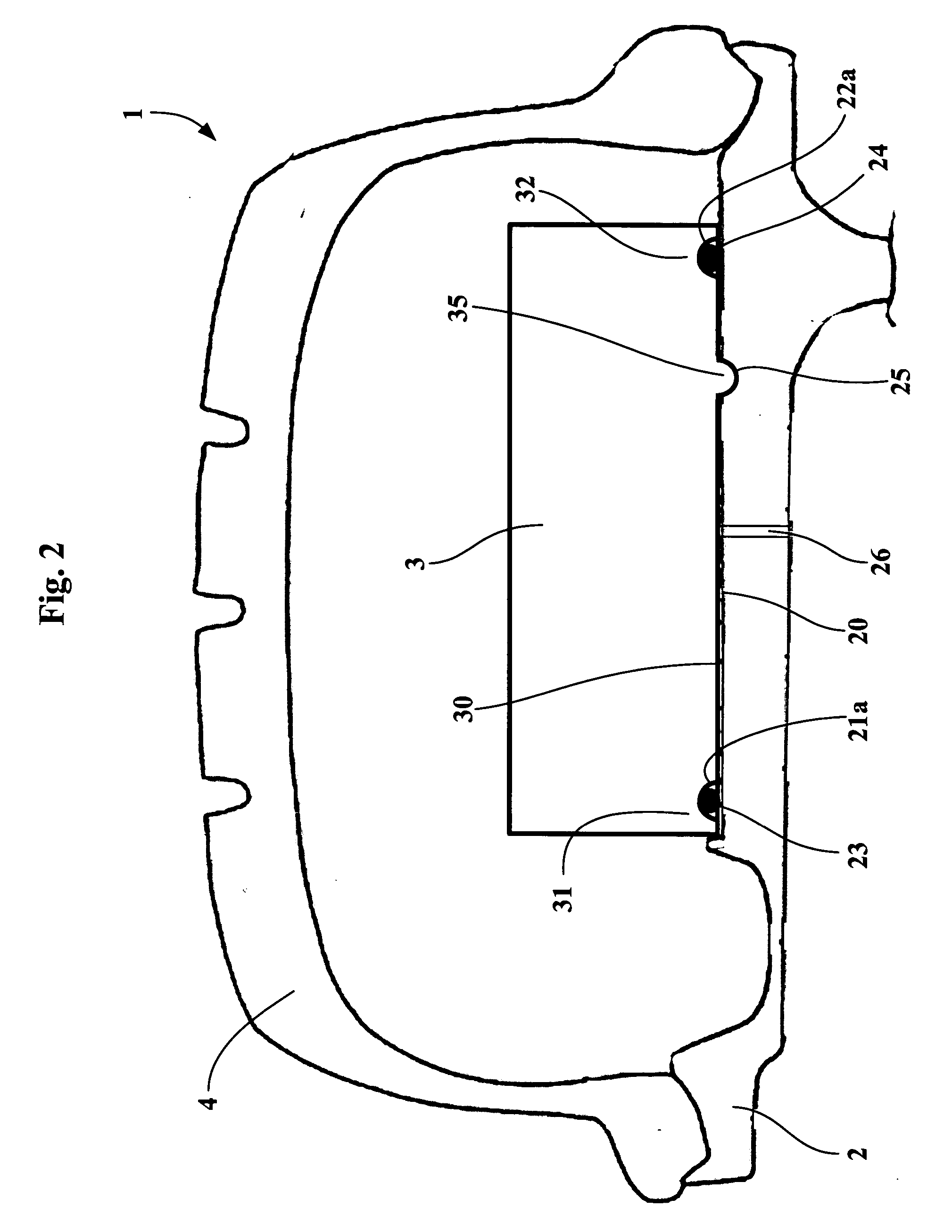
[0016]FIG. 1 shows an assembly 1 comprising a rim 2 equipped with an inflation valve (not shown). A tire 4 is mounted on said rim 2 and a structural support 3 is mounted on the rim in the internal space defined by the inner surface of the tire and the rim.

[0017] The two opposite axial ends 31 and 32 of the support form an airtight joint with the rim. To this end, two circumferential grooves 21 and 22 are disposed on the rim in line with the ends 31 and 32 of the support. O-ring seals 23 and 24 are placed in the cavities of the grooves 21 and 22 and form airtight joints with the base 30 of the support 3. A duct 26 makes it possible to connect the space between the rim 20 and the base 30 and situated axially between the two airtight joints with the atmosphere.

[0018] To prevent the support from moving in the axial direction, it is advisable to form on the rim 3 an additional circumferential groove 25 disposed between the airtight joints provided a...


PUM


Abstract

A safety assembly (1) for a tire allowing running at reduced pressure. A rim (2) is equipped with a valve, and a tire (4) is mounted on the rim. A structural support (3) rests on the rim (2) and is enclosed in the space between the rim and the internal wall of the tire. The two axially opposed ends (31, 32) of the base (30) of the support (3) form an airtight joint with the part of the rim (2) on which they rest. The space between the rim (20) and the base of the support (30) and situated between the two airtight joints communicates with atmospheric pressure by means of a duct (26).

Description

FIELD OF THE INVENTION [0001] The invention relates to safety assemblies allowing running at reduced pressure and comprising a rim, said rim being equipped with a valve, a tire mounted on the rim, and a structural support resting on the rim and enclosed in the space between the rim and the internal wall of the tire. BACKGROUND OF THE INVENTION [0002] These assemblies and the original elements of which they are composed are known from the prior art and are described in publications EP 0 748 287, EP 0 736 747 or alternatively EP 1 206 357. [0003] These publications disclose safety assemblies allowing running at reduced pressure. In addition to research into the best compromise ensuring the sought-after safety functions, these publications also disclose particular embodiments of the rim and of the support aimed at reducing the total mass of the assembly. [0004] The rims used in the assemblies described above may equally well be of the type with the seat inclined towards the inside or t...

Claims


Application Information

Patent Timeline
IPC IPC(8): B60C17/04B60B30/02
CPCB60C17/06
Inventor TRAMOND, PHILIPPELACOUR, JEAN-CHARLES
Owner MICHELIN RECH & TECH SA
Learn More