Light-source driving method and projector

a driving method and light source technology, applied in the field of light source driving method and projector, can solve problems such as flickering projection images, and achieve the effect of correcting auto-focus adjustmen

Inactive Publication Date: 2007-01-04
SEIKO EPSON CORP
View PDF29 Cites 14 Cited by
  • Summary
  • Abstract
  • Description
  • Claims
  • Application Information

AI Technical Summary

Benefits of technology

[0010] Consequently, when carrying out an auto-focus adjustment, the image data taken of a projection image, for example, by an imaging device can be provided constant in lightness by driving the light source on the drive waveform for auto-focus adjustment. Meanwhile, in the ordinary time, light source is driven on the drive waveform for usual time thereby enabling to project a projection image free of flicker.
[0016] Consequently, when carrying out an auto-focus adjustment, the image data taken of a projection image, for example, by an imaging device can be provided constant in lightness by driving the light source on the drive waveform for auto-focus adjustment. Meanwhile, in the ordinary time, light source is driven on the drive waveform for usual time thereby enabling to project a projection image free of flicker.
[0019] Consequently, when performing an auto-focus adjustment, the image data taken of a projection image, for example, by means of an imaging device can be provided constant in lightness by driving the light source on the first drive waveform. Meanwhile, in the ordinary time, light source is driven on the second drive waveform thereby enabling to project a projection image free of flicker.
[0022] Consequently, in the case of imaging a projection image by using an imaging device, etc. and making a detection of the image data thus taken to thereby performing an auto-focus adjustment of the projection image on the basis of the detection result, the current-control instructing section is allowed to make a controllable instruction for switching the second drive waveform for ordinary time into a first drive waveform for auto-focus adjustment. Meanwhile, when the auto-focus adjustment completes, it is possible to provide a controllable instruction for switching into a second drive waveform as a drive waveform for the ordinary time. As a result, because the lightness on each of the image data taken can be provided constant in lightness, correct detection and hence correct auto-focus adjustment can be made on the projection image. Meanwhile, in the ordinary time, a projection image free of flicker can be projected.
[0025] Consequently, when performing an auto-focus adjustment, the current-control instructing section makes a switching into a first drive waveform and drives the light source. Consequently, when the image acquiring section receives a reflection light of the projection image and acquires it as image data, the lightness of each of the image data acquired can be provided constant in lightness. As a result, the image processing section makes an analytic processing of the image data thereby enabling a correct auto-focus adjustment.
[0028] Due to this, where the light-source driver is mounted on a projector, when imaging a projection image, for example, by using an imaging device and detecting image data thus taken to thereby performing an auto-focus adjustment of the projection image on the basis of the detection result, the current-control instructing section under control of the controlling section is allowed to make a controllable instruction for switching the drive waveform outputted by the light-source driving section into a first drive waveform for auto-focus adjustment. As a result, because the lightness on each of the image data taken can be provided constant in lightness, correct detection and hence correct auto-focus adjustment can be made on the projection image. Meanwhile, in the ordinary time, the current-control instructing section makes a controllable instruction for switching into a second drive waveform for ordinary time, thus enabling to project a projection image free of flicker.

Problems solved by technology

However, where electron discharge is sustained at between the lamp electrodes for a long time, discharge path becomes instable to cause flicker on the projection image.

Method used


Image

  • Light-source driving method and projector
  • Light-source driving method and projector
  • Light-source driving method and projector

Examples


first embodiment

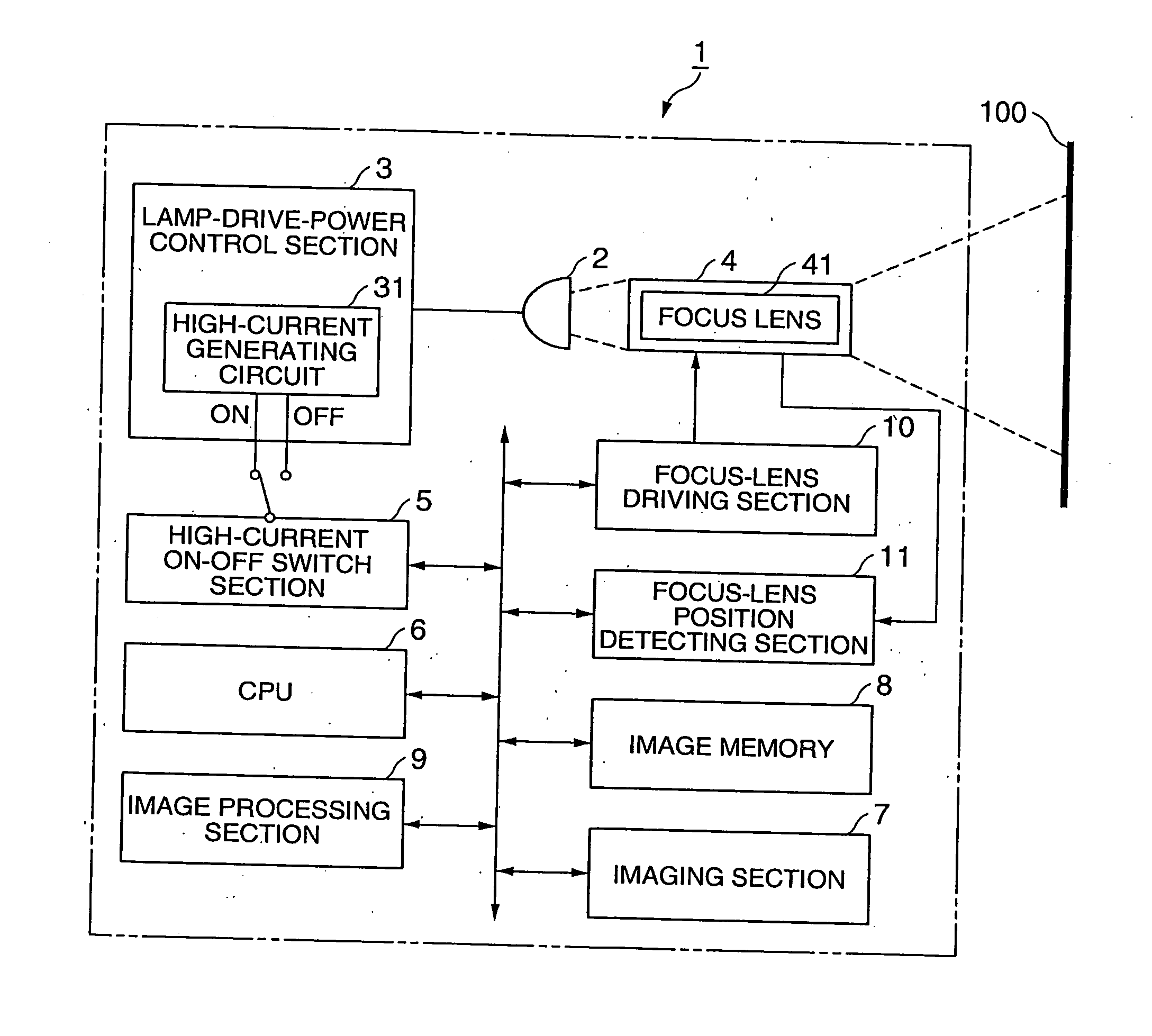
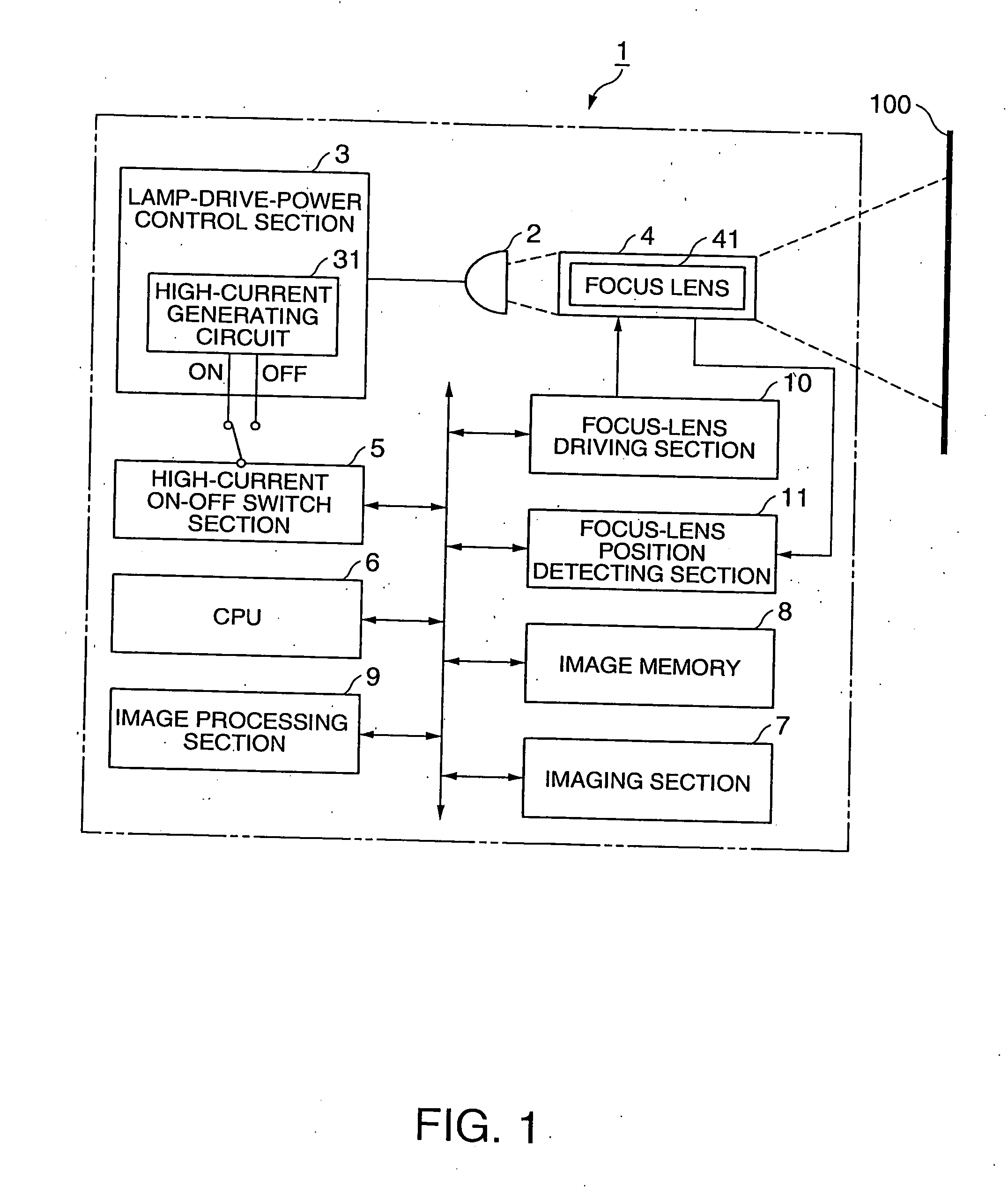
[0038]FIG. 1 is a schematic arrangement diagram for carrying out an auto-focus adjustment by use of a lamp drive-power control section as a light-source driving section on a projector.

[0039] Using FIG. 1, explanation is made on the construction of a projector 1.

[0040] The projector 1 has a lamp 2 as a light source for emitting light, an optical system (not shown) for polarization-converting and color-separating the emission light of the lamp 2 so that those of light are modulated by a spatial light modulation element and combined together, and a projection lens 4 for projecting the combined light through magnification. Thus, an image as combined light is projected onto a screen 100 set up on a wall or the like.

[0041] Meanwhile, the projector 1 has a lamp-drive-power control section 3 as a light-source driving section for supplying power to the lamp 2. Also provided is a high-current on-off switch section 5 as a current-control instructing section for controllably instructing, for...

second embodiment

[0079] Explanation is now made on a second embodiment of the invention, based on the drawings.

[0080]FIG. 6 is a schematic arrangement diagram for performing an auto-zoom adjustment by using a lamp-drive-power control section as a light-source driving section on the projector. Using FIG. 6, explained is the arrangement of the projector 1.

[0081] The arrangement of FIG. 6 is explained on the arrangement different from the arrangement of the FIG. 1. The constituent elements like those of FIG. 1 are attached with like references.

[0082] The arrangement different from the arrangement of FIG. 1 lies in that the focus lens 41 is replaced with a zoom lens 42, the focus-lens driving section 10 is with a zoom-lens driving section 12, and the focus-lens position detecting section 11 is with a zoom-lens position detecting section 13. The other arrangement is similar to FIG. 1.

[0083]FIG. 7 is a flowchart for performing an auto-zoom adjustment. Meanwhile, the steps S101 and the subsequent in th...


PUM


Abstract

To provide a light-source driving method for supplying power to a light source of a projector and a projector employing the light-source driving method there are provided a lamp-drive-power control section (3) as a light-source driving section for outputting a first drive waveform and a second drive waveform, and a high-current on-off switch section 5 as a current-control instructing section for making a controllable instruction to switch the first drive waveform and second drive waveform outputted from the lamp-drive-power control section (3).

Description

TECHNICAL FIELD [0001] The present invention relates to a light-source driving method for supplying power to a light source of a projector, and to a projector using the light-source driving method. BACKGROUND ART [0002] The light source of a projector generally employs a discharge-schemed lamp to emit light with intensity. However, where electron discharge is sustained at between the lamp electrodes for a long time, discharge path becomes instable to cause flicker on the projection image. In such a circumstance, there is a light-source driver having a function to stabilize the discharge path and prevent against flicker by carrying out a drive to supply regularly a usual current and a greater amount of current as compared to the usual current, at the end of the light-source driver for supplying power to and putting on (driving) the lamp (see Patent Document 1 (FIG. 4)). There is another consideration to flow a greater amount of current as compared to that in the initial stage of peri...

Claims


Application Information

Patent Timeline
Patent Type & Authority Applications(United States)
IPC IPC(8): G03B21/20
CPCH04N5/74H05B41/2928H04N9/317H04N9/3155G03B21/00G03B21/14H05B41/38
Inventor MATSUMOTO, MORIOFURUI, SHIKI
Owner SEIKO EPSON CORP
Why Eureka
Try Eureka