Head assembly of golf club

Inactive Publication Date: 2007-01-04
LEE JAE YOUNG +2
View PDF0 Cites 21 Cited by
  • Summary
  • Abstract
  • Description
  • Claims
  • Application Information

AI Technical Summary

Benefits of technology

[0016] Since the head assembly of a golf club in accordance with the present invention includes a sound generating device or a vibration generating device installed to a head, the golfer can utilize their senses

Problems solved by technology

Since the golfer's personality influences their golf game, it is difficult to gain skill in golf.
In particular, when novices swing a golf club they may become accustomed to an undesirable golf pose.
As such most novices have difficulty in improving their swing.
Although novices consciously try to learn proper swing technique according to the various factors, sinc

Method used


Image

  • Head assembly of golf club
  • Head assembly of golf club
  • Head assembly of golf club

Examples


embodiment 1

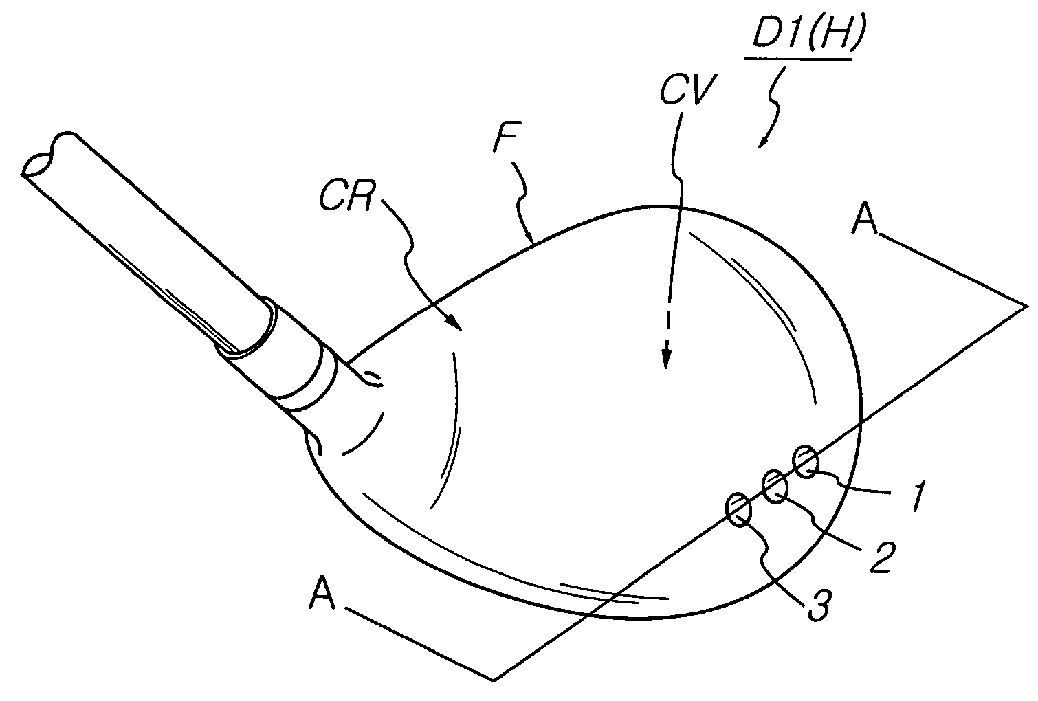
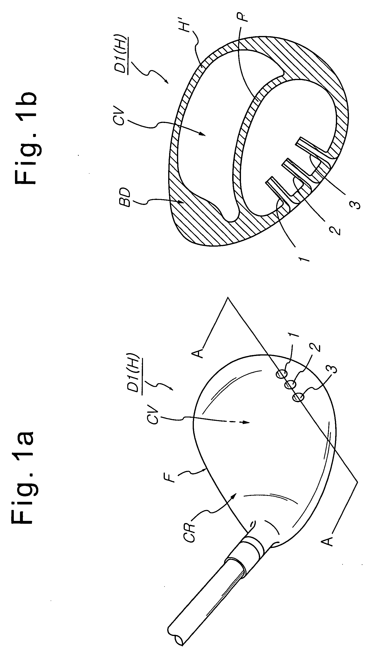
[0051]FIG. 1a shows a head assembly of a golf club according to a first preferred embodiment of the present invention applied to a head H of a driver D1. The head assembly, according to the first preferred embodiment of the present invention, is applied to the driver D1 having a cavity CV formed in the driver D1. The head assembly according to this embodiment includes plural sound pipes 1, 2, and 3, which are extended from the back of a face F of the head H to the cavity CV of a body BD of the driver D1 and are fixed to the body BD.

[0052] Moreover, as shown in FIG. 1b illustrating a first modification of the head assembly of a golf club according to the first preferred embodiment of the present invention, the sound pipes 1, 2, and 3 are integrally fixed to a wall H′ for forming the driver D1. The first modification of the head assembly further includes a partition P installed to the intermediate portion of the cavity CV and to divide the cavity CV into two spaces so as to separate ...

embodiment 2

[0061]FIGS. 2a is a perspective view illustrating a head assembly of a golf club according to a second preferred embodiment of the present invention applied to a driver. The second preferred embodiment is described together with various modifications.

[0062] A head H of a driver D9 includes a cavity CV formed in the head H, and a resonant wall W installed in the cavity CV of a body BD connected to a face F of the head to generate sound. The resonant wall W is a metal wall with a sufficient thin thickness for dividing the cavity CV into two hollow spaces G1 and G2. The resonant wall W is made of the same material as that of the head H of the driver D9 and is integrally formed with the head H or is separately made of a resonant metal plate and fixed in the cavity CV.

[0063] As shown FIG. 2b, a driver D10 of a first modification of the head assembly of a golf club according to the second preferred embodiment of the present invention includes a plurality of resonant walls W1 and W2. As ...

embodiment 3

[0067] Generally, drivers D are manufactured via mechanical processes such as molding, forging, or the like. As shown in FIG. 3s, a head H of a driver D15, employing a head assembly of a golf club according to a third preferred embodiment of the present invention, includes a face F and a body BD connected to the face F to form a cavity CV therein. The body BD is integrally formed with the face F or is fixed to the face F.

[0068] The head assembly of a golf club according to the third preferred embodiment of the present invention further includes a vibration generating device R installed in the cavity CV. The vibration generating device R, as shown in FIG. 3b, includes an elastic connection rod 60 such as a coil spring installed to a center of gravity G of the rear face of the face F in the cavity CV formed in the body BD, and a metal ball, such as a steel ball, fixed to a free end of the elastic connection rod 60.

[0069] The vibration generating device R of a modification of the hea...


PUM


Abstract

The head assembly of a golf club includes a sound generator or a vibration generator. The sound generator includes a sound hole formed in a head of a driver, a sound pipe attached to the head, and a sound generator attached to an iron. Using the head assembly, since the golfer slowly swings the golf club, improper rapid swing is prevented and head-up is also minimized.

Description

BACKGROUND OF THE INVENTION [0001] 1. Field of the Invention [0002] The present invention relates to a head assembly of golf clubs, and more particularly, to an improvement of a head of various golf clubs such as drivers, irons, and putters, and fairway woods to enable a golfer to improve their swing and to efficiently use the golf clubs. [0003] 2. Description of the Related Art [0004] Golf is often referred to as a “mind game”, and a golfer's state of mind is of primary importance in the game of golf. Since the golfer's personality influences their golf game, it is difficult to gain skill in golf. In particular, when novices swing a golf club they may become accustomed to an undesirable golf pose. As such most novices have difficulty in improving their swing. [0005] Generally, there are various important factors in playing golf, which golfers have difficulty in easily learning, as follows. First, a golf club must be slowly backswung so as to precisely drive a golf ball along a pred...

Claims


Application Information

Patent Timeline
IPC IPC(8): A63B53/00
CPCA63B53/0466A63B2053/0454A63B53/0487A63B59/0088A63B59/0092A63B69/3632A63B69/3635A63B69/3685A63B2053/0495A63B2071/0625A63B2071/0633A63B2225/01A63B2053/045A63B49/06A63B53/047A63B60/52A63B60/54A63B60/50A63B53/0454A63B53/045
Inventor LEE, JAE-YOUNGLEE, JAE-GUENLEE, JAE-HWAN
Owner LEE JAE YOUNG
Why Eureka
Try Eureka