Aspiration control

a microsurgical and aspiration control technology, applied in the field of aspiration control, can solve the problems of slow response time, vacuum controlled systems are difficult to operate in flow control mode, and lack of occlusion detection

Active Publication Date: 2007-01-04
ALCON INC
View PDF31 Cites 43 Cited by
  • Summary
  • Abstract
  • Description
  • Claims
  • Application Information

AI Technical Summary

Benefits of technology

[0008] The present invention provides a microsurgical system capable of controlling aspiration via a vacuum control mode, a suction control mode, or a flow control mode.
[0009] In a suction control mode of the present invention, a desired suction pressure is created in an aspiration chamber using a pressurized gas source and a vacuum generator. Fluid is aspirated from a surgical device into the aspiration chamber. An actual suction pressure is determined in the aspiration chamber. A pressure generated by the pressurized gas source and a vacuum generated by the vacuum generator are modified, in response to the actual suction pressure of the determining step, so as to main

Problems solved by technology

Disadvantages of such systems are the lack of flow information resulting in transient high flows during phacoemulsification or fragmentation coupled with a lack of occlusion detection.
Vacuum controlled systems are difficult to operate in a flow controlled mode because of the problems of non-invasively measuring flow in real time.
Disadvantages of such systems are relatively slow response times, unde

Method used


Image

  • Aspiration control
  • Aspiration control

Examples


Embodiment Construction

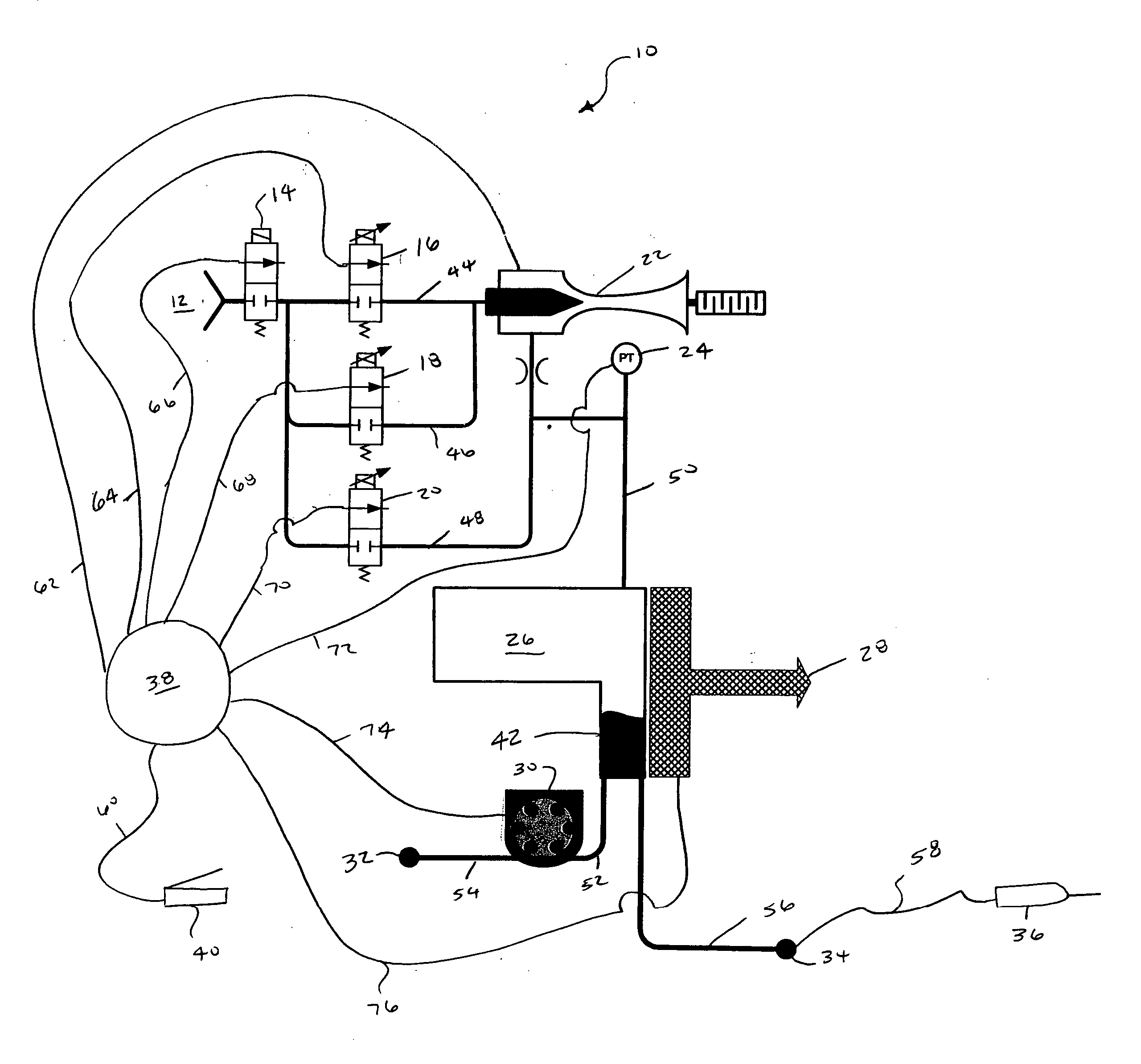
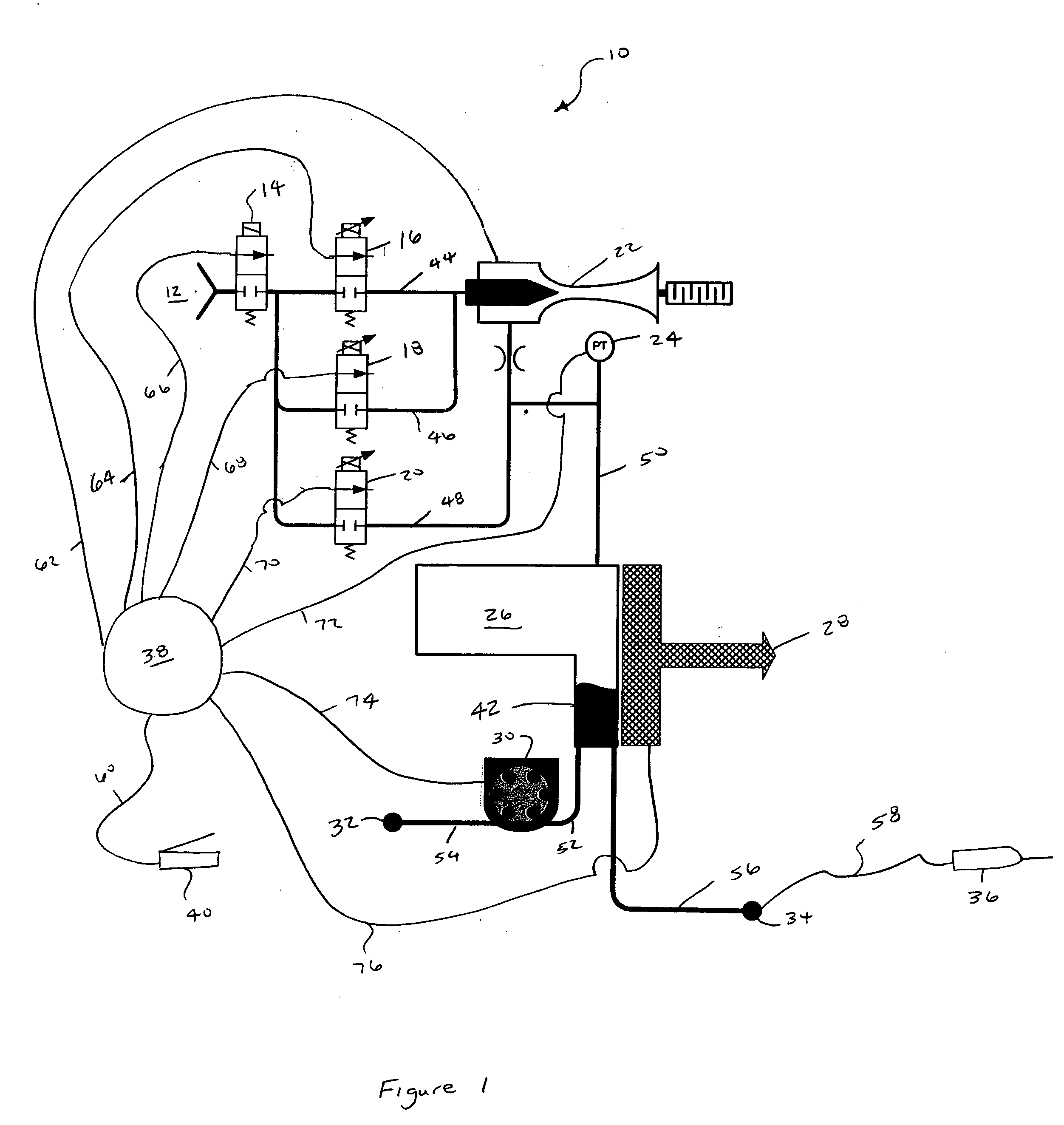
[0012] The preferred embodiment of the present invention and its advantages is best understood by referring to FIG. 1 of the drawings. Microsurgical system 10 includes a pressurized gas source 12, an isolation valve 14, a vacuum proportional valve 16, an optional second vacuum proportional valve 18, a pressure proportional valve 20, a vacuum generator 22, a pressure transducer 24, an aspiration chamber 26, a fluid level sensor 28, a pump 30, a collection bag 32, an aspiration port 34, a surgical device 36, a computer or microprocessor 38, and a proportional control device 40. The various components of system 10 are fluidly coupled via fluid lines 44, 46, 48, 50, 52, 54, 56, and 58. The various components of system 10 are electrically coupled via interfaces 60, 62, 64, 66, 68, 70, 72, 74, and 76. Valve 14 is preferably an “on / off” solenoid valve. Valves 16-20 are preferably proportional solenoid valves. Vacuum generator 22 may be any suitable device for generating vacuum but is prefe...


PUM


Abstract

A microsurgical system capable of controlling aspiration via a vacuum control mode, a suction control mode, or a flow control mode.

Description

FIELD OF THE INVENTION [0001] The present invention generally pertains to controlling aspiration in microsurgical systems and more particularly to controlling aspiration in ophthalmic microsurgical systems. DESCRIPTION OF THE RELATED ART [0002] During small incision surgery, and particularly during ophthalmic surgery, small probes are inserted into the operative site to cut, remove, or otherwise manipulate tissue. During these surgical procedures, fluid is typically infused into the eye, and the infusion fluid and tissue are aspirated from the surgical site. The types of aspiration systems used, prior to the present invention, were generally characterized as either flow controlled or vacuum controlled, depending upon the type of pump used in the system. Each type of system has certain advantages. [0003] Vacuum controlled aspiration systems are operated by setting a desired vacuum level, which the system seeks to maintain. Flow rate is dependent on intraocular pressure, vacuum level,...

Claims


Application Information

Patent Timeline
IPC IPC(8): A61M1/00
CPCA61M1/0031A61M1/0076A61M1/0035A61M2205/3379A61M1/0027A61M2205/123A61M1/732A61M1/74A61M1/743A61M1/804A61M1/72
Inventor HOPKINS, MARK A.GAO, SHAWN X.
Owner ALCON INC
Why Eureka
Try Eureka