
Modular nut plate

a technology of nut plate and module, which is applied in the direction of ligaments, prostheses, osteosynthesis devices, etc., can solve the problems of difficult affixing of difficult access to nut heads, and difficulty in affixing single nuts or bolts to complete assemblies, etc., and achieves efficient and inexpensive manufacturing.

Inactive Publication Date: 2007-01-04
ILLINOIS TOOL WORKS INC
View PDF11 Cites 2 Cited by
  • Summary
  • Abstract
  • Description
  • Claims
  • Application Information

AI Technical Summary

Benefits of technology

[0011] An advantage of the present invention is providing a modular nut plate which can be manufactured efficiently and inexpensively.
[0012] Another advantage of the present invention is providing a modular nut plate having a carrier that can be used with different types and sizes of connector assemblies.
[0013] Still another advantage of the present invention is providing a modular nut plate that can be connected in end-to-end relationship of infinite lengths.
[0014] Other features and advantages of the invention will become apparent to those skilled in the art upon review of the following detailed description, claims and drawings in which like numerals are used to designate like features.

Problems solved by technology

In many situations, it is difficult to access a nut, bolt head or other fastener component to complete an assembly.
Affixing a single nut or bolt can be difficult, and positioning of it can be imprecise.
Further, although the nut portion might be required to be of metal or other strong, durable material, the plate portion of a nut plate is needed primarily for positioning purposes and may not have the same requirements of strength and durability.
However, if the nut plate is a monolithic body, the plate portion is of the same material, thus adding to cost of the nut plate.
This again has added to both expense and inconvenience in that many different types of nut plates may be required.

Method used


Image

  • Modular nut plate
  • Modular nut plate
  • Modular nut plate

Examples


Embodiment Construction

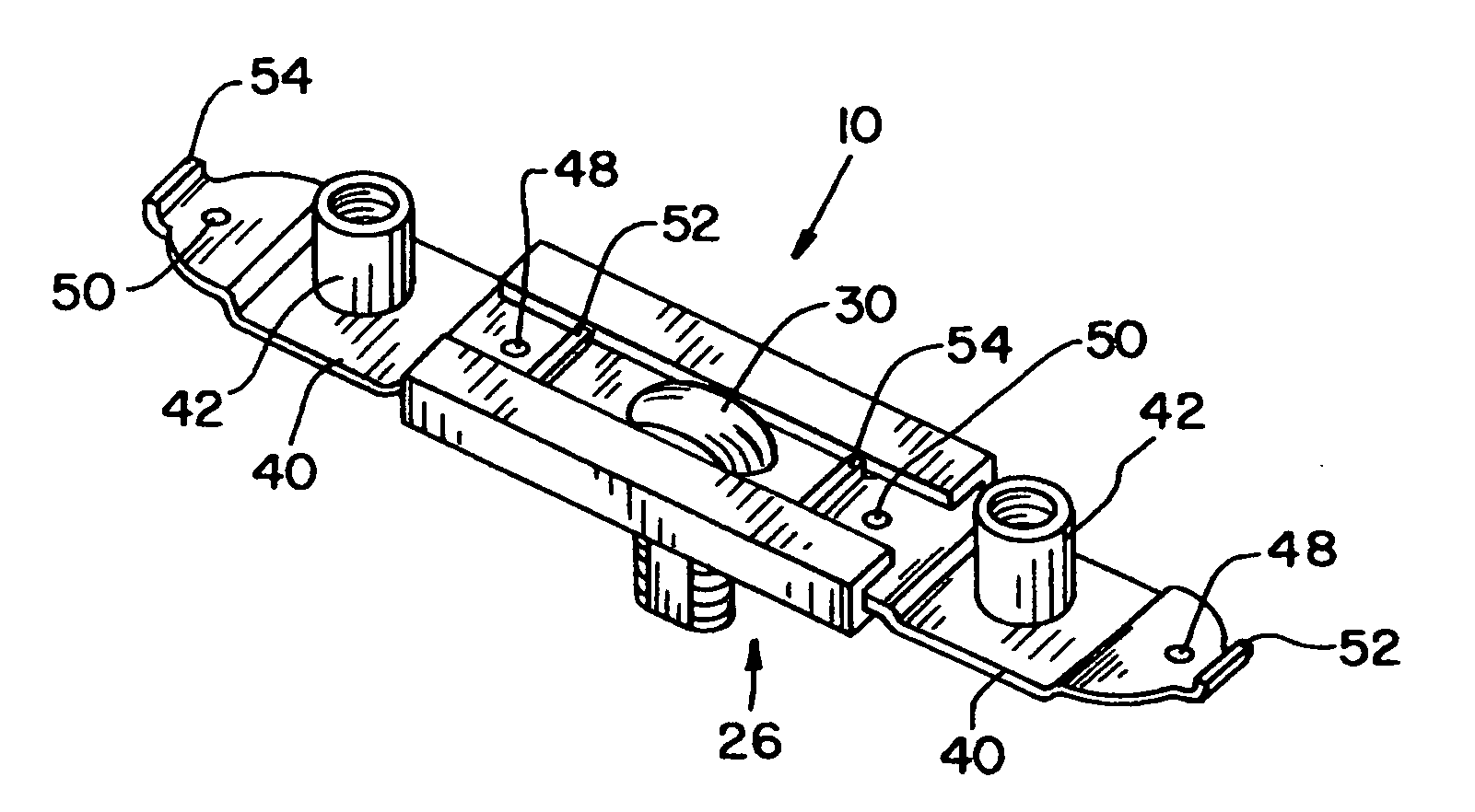
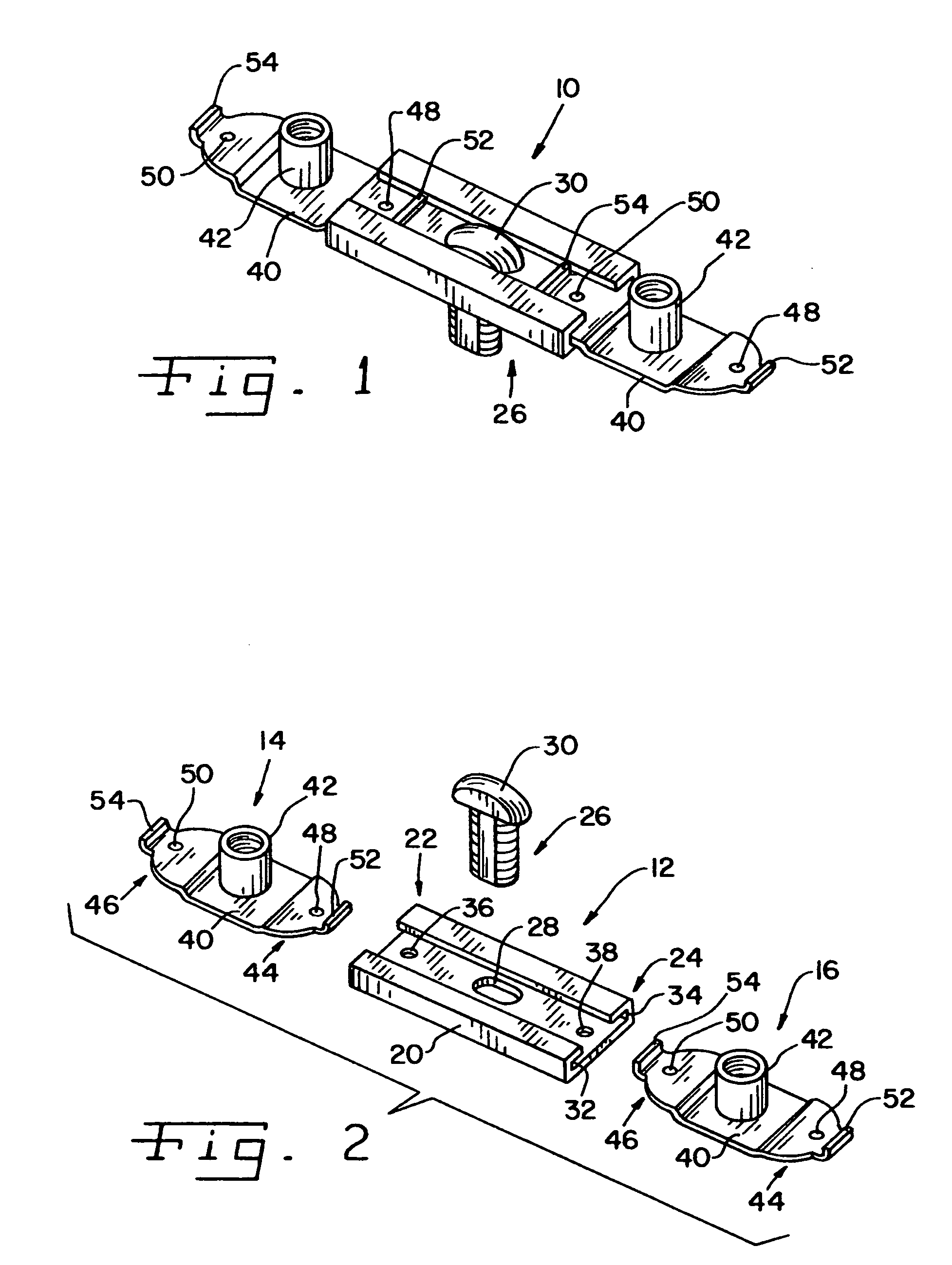
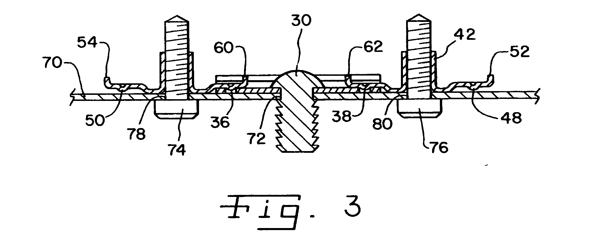
[0019] Referring now more specifically to the drawings and to FIG. 1 in particular, a modular nut plate 10 in accordance with the present invention is shown. Nut plate 10 includes a carrier 12, a first fastener component 14 connected at one end of carrier 12 and a second fastener component 16 connected at an opposite end of carrier 12 from the end at which fastener component 14 is connected. Since nut plate 10 is modular, the individual components thereof can be made of material most suitable for the requirements of the component. For example, carrier 12 can be made of plastic and fastener components 14 and 16 can be made of metal. Alternatively, one or both of fastener components 14 and 16 can be made of plastic and / or carrier 12 can be made of metal.

[0020] In the exemplary embodiment, carrier 12 is an elongate body 20 having firs and second connector sites 22 and 24 at opposite ends thereof. A mounting structure 26 includes an elongate hole 28 and a pin 30 for insertion and there...


PUM


Abstract

A modular nut plate includes a carrier configured for mounting the nut plate and fastener components selectably connectable to the carrier. Multiple nut plates can be linked together end to end.

Description

CROSS-REFERENCE TO RELATED APPLICATIONS [0001] The present regular U.S. Patent Application claims the benefits of U.S. Provisional Application Ser. No. 60 / 671,746, filed on Jun. 17, 2005.FIELD OF THE INVENTION [0002] The present invention relates generally to industrial fastener systems; and, more particularly, the invention pertains to so-called “nut plates” that provide a one or a plurality of fastener sites on a single device connected in an assembly. BACKGROUND OF THE INVENTION [0003] Assemblies of various types such as, for example, automobiles, appliances and the like, use so-called “nut plates” as part of a fastener system. In many situations, it is difficult to access a nut, bolt head or other fastener component to complete an assembly. As a remedy to this difficulty, it is known to secure the nut, bolt or other component in a fixed position for engagement with the complimentary component of the fastener system. Affixing a single nut or bolt can be difficult, and positioning...

Claims


Application Information

Patent Timeline
Patent Type & Authority Applications(United States)
IPC IPC(8): A61F2/30
CPCF16B37/045F16B37/044
Inventor JOHNSON, LAWRENCE W.WOCHASKI, EDWARD J.
Owner ILLINOIS TOOL WORKS INC
Learn More