Automatic interdental cleaner

a technology of interdental cleaning and cleaning brush, which is applied in the field of automatic interdental cleaning, can solve the problems of interdental brush not cleaning between teeth in the desired state, gums may be hurt by dental floss, etc., and achieve the effect of effectively cleaning between teeth and not hurting gums between teeth

Inactive Publication Date: 2007-01-11
KANG YOUNG HAN
View PDF17 Cites 17 Cited by
  • Summary
  • Abstract
  • Description
  • Claims
  • Application Information

AI Technical Summary

Benefits of technology

[0012] The present invention is disclosed to solve the aforementioned problems and it is an object of the present invention to provide an automatic interdental cleaner adapted not to hurt gums between teeth and to effectively clean between the teeth as well.

Problems solved by technology

However, there is a problem in the interdental brushes thus described according to the prior art in that gums may be hurt by dental floss or thin synthetic resin piece when an excessive force is applied to the gums.
There is another problem in that the interdental brushes may not clean between teeth in the desired state due to inattention by a user.

Method used


Image

  • Automatic interdental cleaner
  • Automatic interdental cleaner
  • Automatic interdental cleaner

Examples


first embodiment

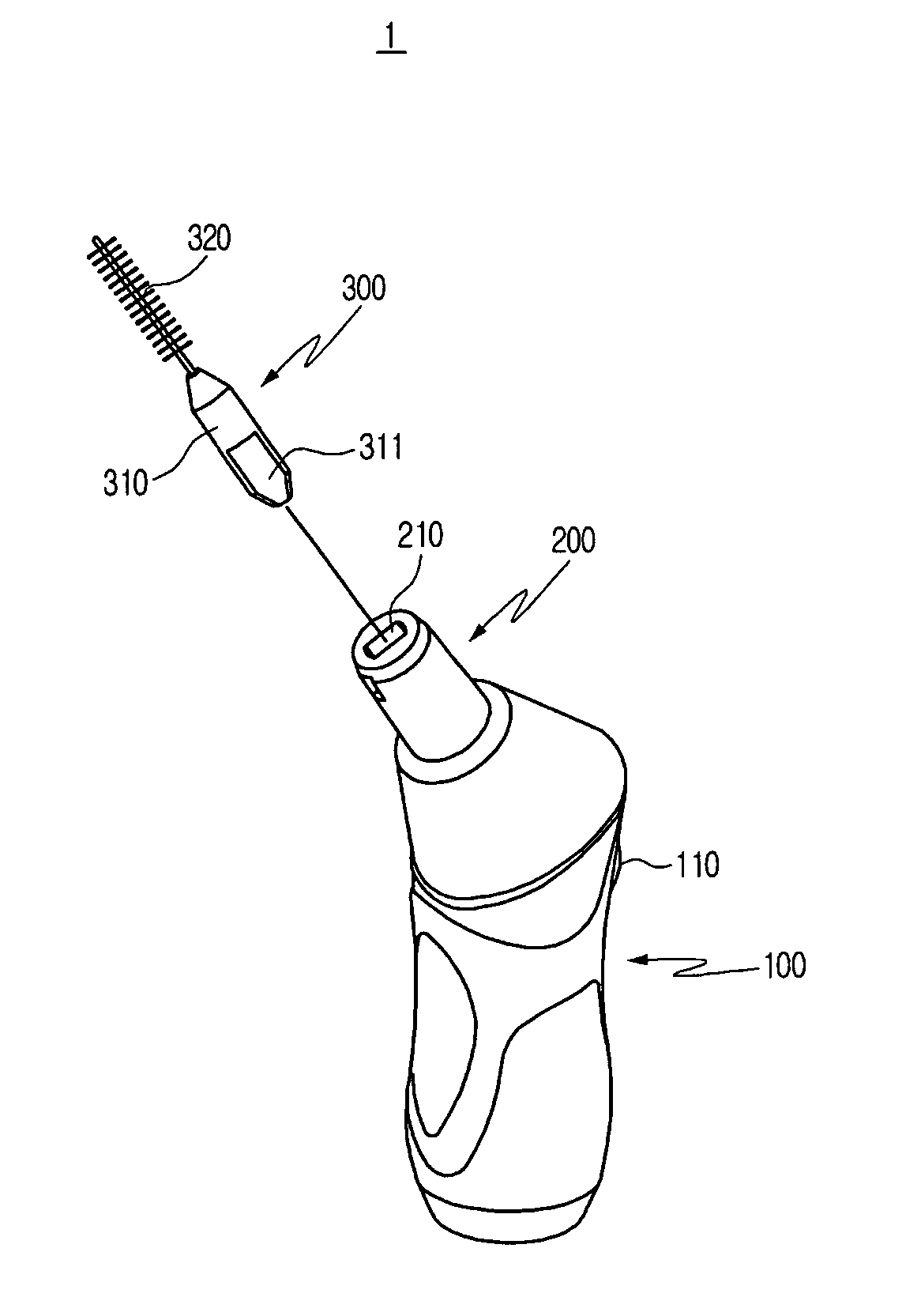
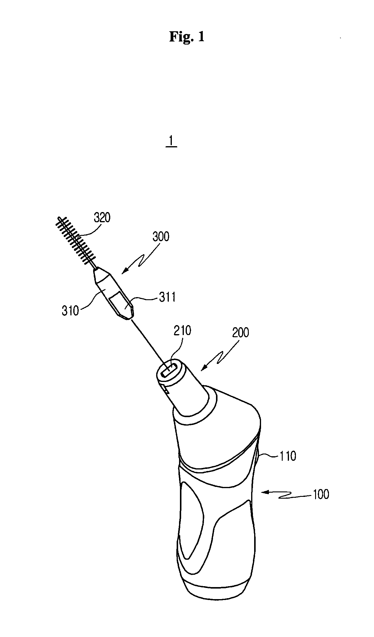
[0028]FIG. 1 is a perspective view for schematically illustrating an automatic interdental cleaner 1 according to the present invention and FIG. 2 is a perspective view of an interdental brush portion 300 of FIG. 1.

[0029] Referring to FIG. 1, an automatic interdental cleaner 1 according to the first embodiment of the present invention includes a grip portion 100, a power transmitting unit 200 and an interdental brush portion 300.

[0030] The grip portion 100 is disposed therein with a battery (not shown) and a motor (not shown). The grip portion 100 is disposed at one lateral wall thereof with a power switch 110 that is circuitally connected to the battery (not shown) and the motor (not shown).

[0031] The power transmitting unit 200 is cylindrically shaped and coupled to one end of the grip portion 100. The power transmitting unit 200 receives the power from the motor (not shown) formed inside the grip portion 100 on switching and vibrates thereby.

[0032] A free end of the power tran...

second embodiment

[0041] Now, referring to FIGS. 3 to 5, the automatic interdental cleaner according to the present invention will be described. The same reference numerals refer to the same parts or portions throughout the various figures, and explanation of the same elements will be briefed.

[0042]FIG. 3 is a perspective view for schematically illustrating an automatic interdental cleaner according to a second embodiment of the present invention, FIG. 4 is a plan view of an adapter portion 400 of FIG. 3, and FIG. 5 is a lateral view of the adapter portion 400 of FIG. 3.

[0043] Referring to FIG. 3, an automatic interdental cleaner 2 according to the second embodiment of the present invention includes a grip portion 100, a power transmitting unit 200, an interdental brush portion 300 and an adapter portion 400.

[0044] The grip portion 100 is disposed therein with a battery (not shown) and a motor (not shown). The grip portion 100 is disposed at one lateral wall thereof with a power switch 110 that is ...


PUM


Abstract

An automatic interdental cleaner for cleaning between teeth more effectively and cleanly without hurting the gum between the teeth is disclosed. The cleaner comprises: a grip portion disposed therein with a battery and a motor and a power switch at one wall side; a power transmitting unit coupled to one end of the grip portion for supplying power from the grip portion and formed with a first insertion hole at a free end; an interdental brush portion including a brush holder having a shape corresponding to that of the first insertion hole of the power transmitting unit and also having one end insertedly fixed to the first insertion hole, and a brush fixed to the other end of the brush holder; and an adapter portion one end of which is coupled to the power transmitting unit and the other end of which accepts the interdental brush portion, such that spaces between the teeth can be automatically cleaned using the automatic interdental cleaner.

Description

CROSS-REFERENCE TO RELATED APPLICATION [0001] Not applicable. STATEMENT CONCERNING FEDERALLY SPONSORED RESEARCH OR DEVELOPMENT [0002] Not applicable. FIELD OF THE INVENTION [0003] The present invention relates to an automatic interdental cleaner for removing foreign objects between teeth, and more particularly an automatic interdental cleaner adapted to be attached with an interdental brush or an adapter to a grip portion for automatic cleaning between teeth. BACKGROUND OF THE INVENTION [0004] Interdental brushes are used as a part of the teeth-cleaning regimen by coupling an end of a handle with a brush or a dental floss. The interdental brushes are useful for removing food remains or dental calculus between teeth where conventional toothbrushes do not touch. They are also useful for cleaning various dental prostheses, such as braces, around various bridgeworks, and improving the level of a person's oral care hygiene. [0005] The interdental brushes thus explained are disclosed in U...

Claims


Application Information

Patent Timeline
Patent Type & Authority Applications(United States)
IPC IPC(8): A61C15/00
CPCA61C17/3481A61C15/00A61C2204/002
Inventor KANG, YOUNG-HAN
Owner KANG YOUNG HAN
Why Eureka
Try Eureka