Snap hinge for supporting a closure element

a technology of latching element and latching hinge, which is applied in the field of latching hinge for supporting a closure element, can solve the problems of limiting user access to the contents of the compartment, hinges are not free, and the latching is not stable, so as to reduce the structural complexity of the latching element, the latching is stable and sa

Active Publication Date: 2007-01-11
ZETTI DANIELE
View PDF5 Cites 13 Cited by
  • Summary
  • Abstract
  • Description
  • Claims
  • Application Information

AI Technical Summary

Benefits of technology

[0019] The aim of the present invention is to eliminate the drawbacks mentioned above of known hinges, by providing a snap hinge which allows a stable and safe support of a closure element with respect to the structure of a piece of furniture or the like both in a closed configuration and in an open configuration of the hinge, while limiting the structural complexity of said hinge.

Problems solved by technology

The above described snap hinges are not free from drawbacks, including the fact that in the open configuration the spring that acts in opposition to the weight force of the door is subject to partial compression and does not ensure the maximum opening of said door with respect to the cabinet, consequently hindering user access to the content of the compartment.
Also with particular reference to the application of said hinges to doors and cabinets for the interior furnishing of caravans or the like, a further drawback is that the elastic action applied by the spring and suitable to keep the door in a position for closing the compartment of the cabinet is not such as to prevent the accidental opening of the door, for example, when the caravan or the like is moving and on bends, with the consequent escape of the contents from the cabinet.
Said hinges are not free from drawbacks, the first of which is high structural complexity due to the particular type of anchoring by means of the coupling plate, with consequent significant production costs.
Moreover, in order to anchor the hinge to the cabinet or the like it is necessary to use an additional supporting element, which is fixed to one of the walls of said cabinet, thus limiting the possibilities of use of the hinge.

Method used


Image

  • Snap hinge for supporting a closure element
  • Snap hinge for supporting a closure element
  • Snap hinge for supporting a closure element

Examples


Embodiment Construction

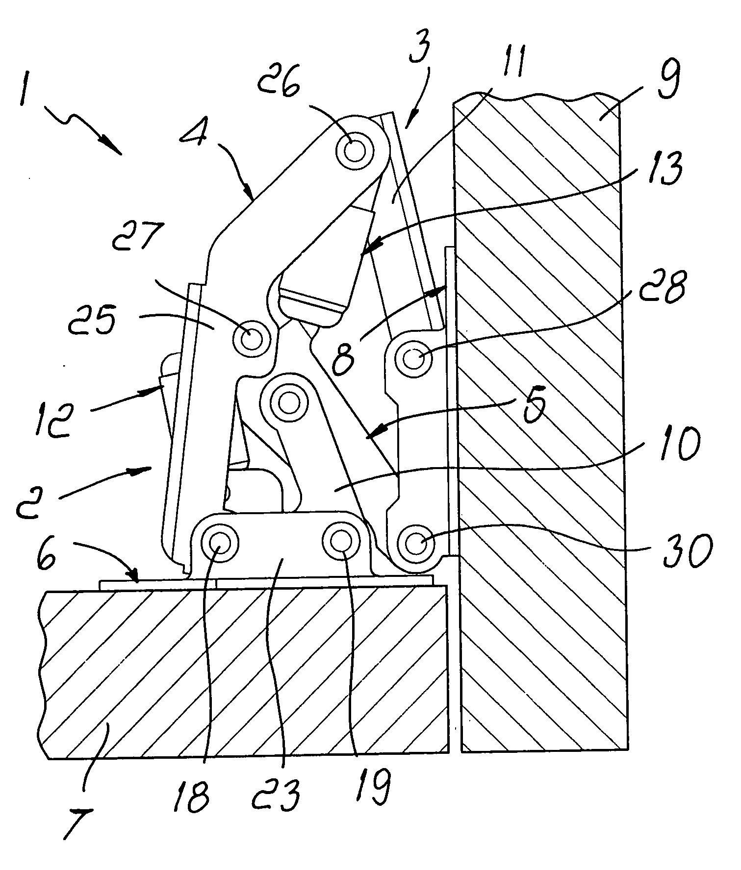
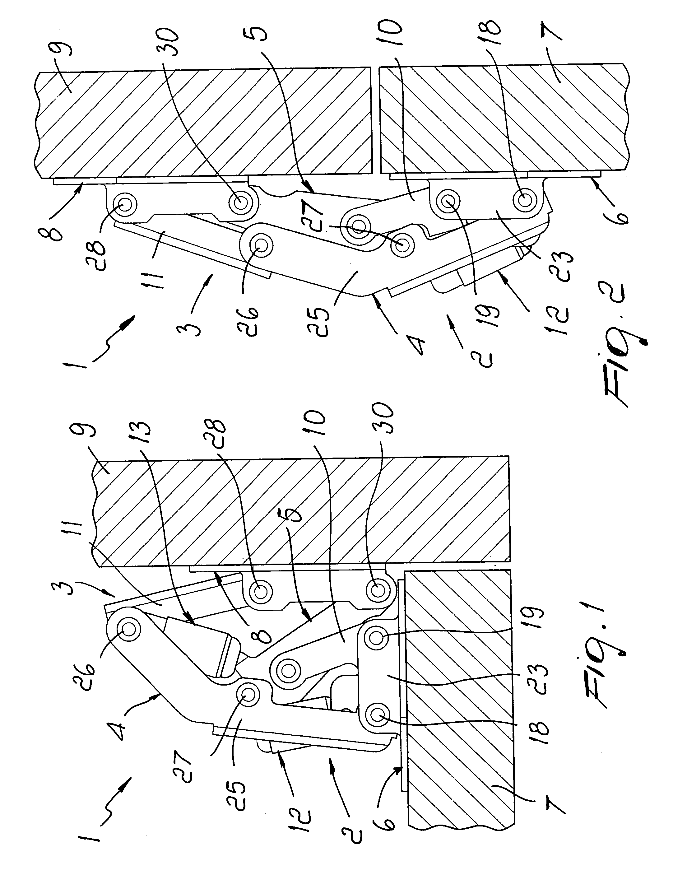
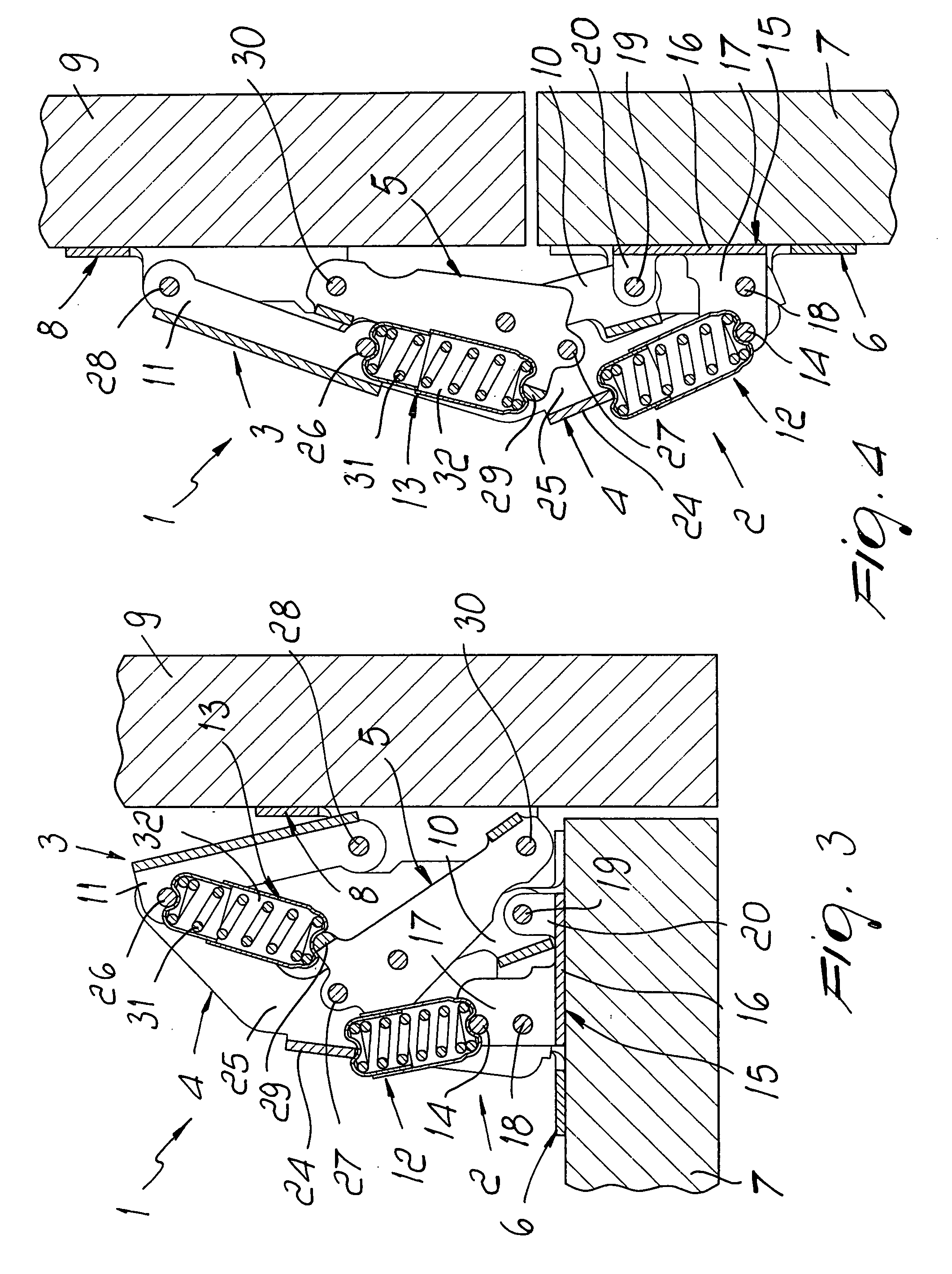
[0029] With reference to the figures, the reference numeral 1 designates a snap hinge.

[0030] The hinge 1 comprises a first articulated quadrilateral 2 and a second articulated quadrilateral 3, which share a first lever 4 and a second lever 5 and have as their base element respectively a plate 6 for coupling to a fixed element 7 and a plate 8 for fixing to a closure element 9.

[0031] With particular but not exclusive reference to cabinets for caravans or the like, the fixed element 7 is constituted by the wall that delimits in an upper region said cabinet and the coupling plate 6 is anchored to the surface of said wall that faces the internal compartment.

[0032] The closure element 9 is instead constituted by a door, and the fixing plate 8 is anchored thereto on the surface that is designed to face the compartment when the door is arranged in a position for closing the cabinet.

[0033] Each of the articulated quadrilaterals 2, 3 further comprises a respective arm.

[0034] In particula...


PUM


Abstract

A snap hinge for supporting a closure element, which comprises a first articulated quadrilateral and a second articulated quadrilateral, which share a first lever and a second lever, which have as their base element respectively a plate for coupling to a fixed element and a plate for fixing to a closure element, an elastic element acting between a point of the first lever and a point of the second lever, and an auxiliary elastic element, arranged in series to the elastic element and has one end articulated to the first lever and the opposite end articulated to an abutment element rigidly associated with the coupling plate.

Description

[0001] The present invention relates to a snap hinge for supporting a closure element. BACKGROUND OF THE INVENTION [0002] In the field of interior furniture, it is known to use snap hinges which are suitable for the rotation of a closure element about a substantially horizontal or inclined axis, such as for example snap hinges used to open and close doors on cabinets arranged inside caravans or the like. [0003] Known snap hinges comprise a first articulated quadrilateral and a second articulated quadrilateral, which share a first lever and a second lever and have as their base element respectively a plate for coupling to a fixed element of a piece of furniture or the like and a plate for fixing to the closure element. [0004] Further, known snap hinges comprise a spring which acts between two mutually opposite points of one of the two articulated quadrilaterals. [0005] Each of the two articulated quadrilaterals is constituted by the first and second levers, by an arm and by a base el...

Claims


Application Information

Patent Timeline
Patent Type & Authority Applications(United States)
IPC IPC(8): E05F1/08
CPCE05D3/16E05D11/1021E05D11/1064E05F1/1253E05Y2900/20Y10T16/53843Y10T16/5476Y10T16/53613Y10T16/53833Y10T16/5383Y10T16/53832
Inventor ZETTI, DANIELE
Owner ZETTI DANIELE
Why Eureka
Try Eureka