Force sensor

Inactive Publication Date: 2007-01-11
HONDA MOTOR CO LTD
View PDF2 Cites 18 Cited by
  • Summary
  • Abstract
  • Description
  • Claims
  • Application Information

AI Technical Summary

Benefits of technology

[0007] In the above-described force sensor, the external or axial force applied to the active sensing portion of the force sensor chip made of a semiconductor substrate or the like can be dampened to a required level by providing a dampening or buffering mechanism that dampens the external force and applies a part of the external force to the force sensor chip. Considerable external force can thereby be detected. The dampening mechanism that has an external force buffering effect functions as a principal component of the buffering device in a force sensor. Such a buffering device can be manufactured in the form of a cube, cylinder, disc, rod, or other modified shape in accordance with the shape and structure of the dampening mechanism. As a result, a force sensor having such a buffering device can itself be manufactured in various shapes and forms. Force sensors having a large number of variations can expand the range of use and application, and force sensors having an optimal shape and other features can be mounted in the intended location.
[0016] It is preferred that the cylindrical member has a plurality of elongated holes formed in the circumferential direction. The rigidity of the cylindrical member can be appropriately modified by adjusting the shape, number, position, and other features of the holes.
[0018] It is desirable that the dampening mechanism has a plurality of holes formed therein. The rigidity of the dampening mechanism can be appropriately adjusted by appropriately modifying the holes.
[0023] In accordance with the present invention, the force sensor is provided with a buffering device; the buffering device is formed with an input portion, a sensor mount, a transmission portion, and a dampening or buffering mechanism; and the force sensor can be manufactured in a large number of variations by arbitrarily modifying the shape and pattern of the input portion, sensor mount, and dampening mechanism in accordance with usage or application conditions. The axial force applied to the force sensor chip can thereby be appropriately weakened, and the force sensor chip can be installed in an optimal shape and mounting state in accordance with the installation location, installable space, and other factors.

Problems solved by technology

Since a semiconductor sensor chip uses a semiconductor substrate to form a portion that receives external force, there is a limit to the force that can be applied.
When excessive force or moment is applied, the chip on the semiconductor substrate is liable to be damaged.
When a force sensor is furthermore used, for example, in an external force application unit in an industrial robot or the like, an excessively large buffering device cannot be used due to installation space constraints.

Method used


Image

  • Force sensor
  • Force sensor
  • Force sensor

Examples


first embodiment

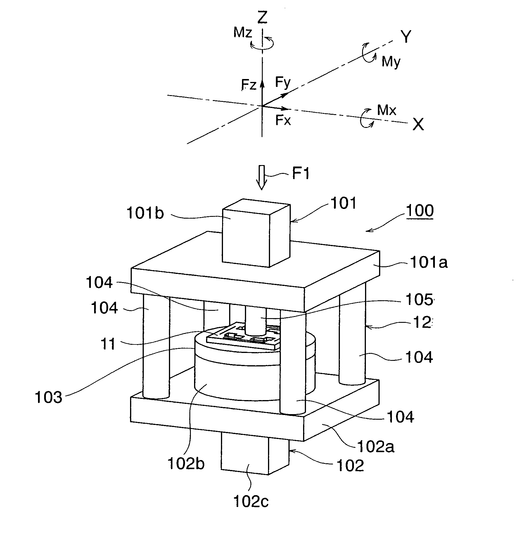
[0062] the force sensor of the present invention is described with reference to FIGS. 1 to 9. The force sensor of this embodiment is cube-shaped.

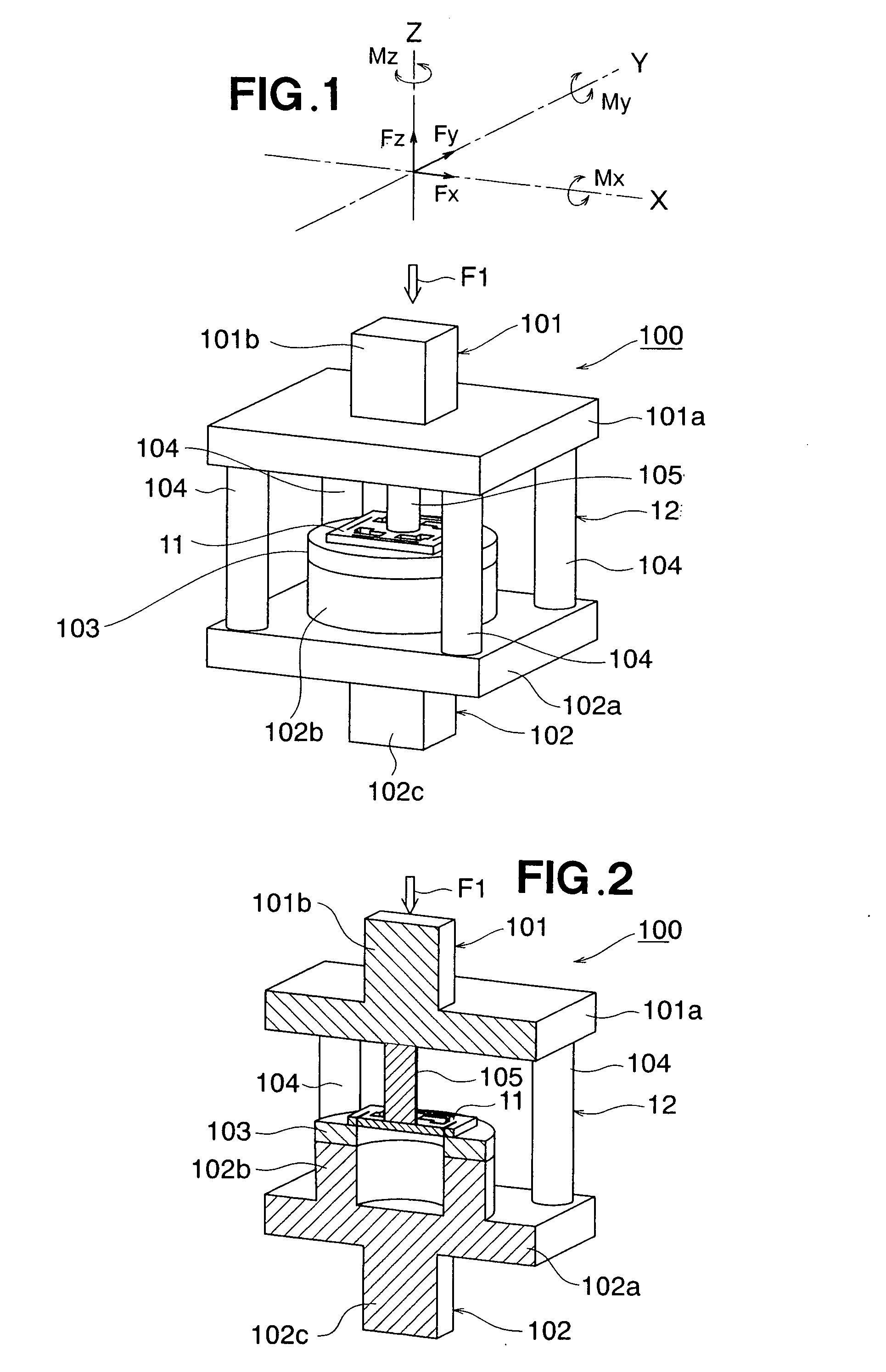
[0063] Following is a description, made with reference to FIGS. 1 and 2, of a force sensor having a simple shape and structure according to the first embodiment. FIG. 1 is an external perspective view of a force sensor 100, and FIG. 2 is a cross-sectional perspective view of the internal structure of the force sensor 100.

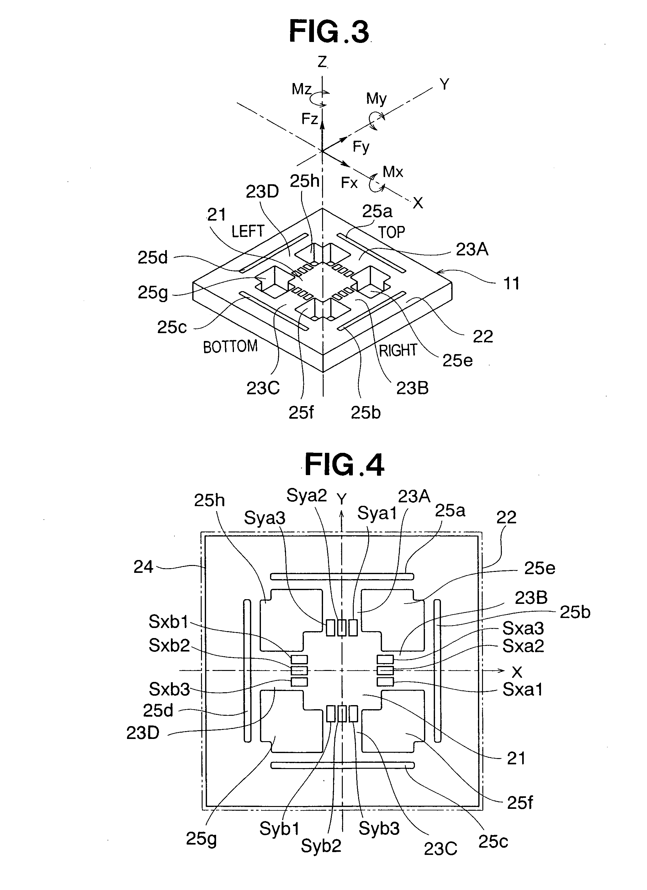
[0064] The main part of the force sensor 100 comprises a force sensor chip 11 and a buffering device 12. An example of the configuration of the force sensor chip 11 is shown in FIGS. 3 and 4. An example of the configuration of the force sensor chip 11 will be described with reference to FIGS. 3 and 4, and the configuration of the force sensor 100 will be described thereafter. The force sensor chip 11 is configured so as to detect external force by using a strain resistance element.

[0065]FIG. 3 shows a perspective view of ...

second embodiment

[0095] the force sensor of the present invention is described next with reference to FIGS. 10 to 15. The force sensor of this embodiment has a cylindrical shape.

[0096] Following is a description, made with reference to FIGS. 10 and 11, of a force sensor 200 having a simple shape and structure according to the second embodiment. FIG. 10 is an external perspective view of a force sensor 200, and FIG. 11 is a cross-sectional perspective view of the internal structure of the force sensor 200. In FIGS. 10 and 11, the same reference numerals are assigned to substantially the same components as those described in the first embodiment, and a description thereof is omitted.

[0097] The main part of the force sensor 200 comprises a force sensor chip 11 and a buffering device 12. The force sensor chip 11 is the same as the one described in the first embodiment. The force sensor 200 is, more specifically, composed of an input portion 201 to which external force (axial force or load) F1 is direct...

third embodiment

[0108] the force sensor of the present invention is described next with reference to FIGS. 16 to 17. The force sensor of this embodiment has a toroidal shape.

[0109] Following is a description, made with reference to FIGS. 16 and 17, of a force sensor 200 having a simple shape and structure according to the third embodiment. FIG. 16 is an external perspective view of a force sensor 300, and FIG. 17 is a cross-sectional perspective view of the internal structure of the force sensor. In FIGS. 16 and 17, the same reference numerals are assigned to substantially the same components as those described in the first embodiment, and a description thereof is omitted.

[0110] The force sensor 300 of this embodiment is principally composed of a force sensor chip 11 and a buffering device 12. The force sensor chip 11 is the same as the one described in the first embodiment. The force sensor 300 is, more specifically, composed of a cylindrical rod-shaped input portion 301 to which external force (...


PUM


Abstract

A force sensor comprises a force sensor chip, and a buffering device for dampening and applying incoming external force to the force sensor chip. The buffering device comprises an input portion to which external force is input, a sensor mount for fixing the force sensor chip to the exterior, a dampening mechanism for dampening external force, and a transmission portion for transmitting the dampened external force to the active sensing portion.

Description

FIELD OF THE INVENTION [0001] The present invention relates to a force sensor, and more particularly relates to a force sensor provided with a buffering device that is suitable for reducing the force applied to a force sensor chip. BACKGROUND OF THE INVENTION [0002] The present inventors have previously proposed a six-axis force sensor disclosed in JP-A-2003-254843. In this six-axis force sensor, buffering devices are disposed about the periphery of the six-axis force sensor so as to reduce the magnitude of external force applied to the external force application portion (force-exerting unit) of the six-axis force sensor chip of the semiconductor substrate. The level of external force that can thereby be measured by the six-axis force sensor is dramatically increased, and the range of application can be expanded. Also, the six-axis force sensor can solve the problem of multiaxial interference even if the structure is provided with a buffering device. [0003] A force / moment detector i...

Claims


Application Information

Patent Timeline
IPC IPC(8): G01L1/26G01L1/22G01L1/14
CPCG01L1/26G01L5/165G01L5/162
Inventor HIRABAYASHI, YUSUKEOHSATO, TAKESHISAKURAI, NOBUHIROYASUIE, SHIGENORIYOKOBAYASHI, HIROSHI
Owner HONDA MOTOR CO LTD
Why Eureka
Try Eureka