Structural camouflage system

a structure and camouflage technology, applied in the field of camouflage, can solve the problems of unsatisfactory need for camouflage, ineffective camouflage designed for one environment, and inability to effectively move to another, so as to prevent any glare

Inactive Publication Date: 2007-01-11
LEWIS ROGER D
View PDF9 Cites 22 Cited by
  • Summary
  • Abstract
  • Description
  • Claims
  • Application Information

AI Technical Summary

Benefits of technology

[0006] The present invention provides a camouflage system that is universally effective for camouflaging essentially any structure in essentially any environment in which it is placed. The system of the invention utilizes, in the preferred embodiment, a camouflage structure formed of a mirrored panels interconnected to form an enclosure in which one or more hunters may conceal themselves, or in which one or more objects to be camouflaged may be placed. Each of the mirrored panels is inclined at an angle of less than ninety degrees relative to the ground or other generally horizontal surface on which the structure is erected. Because of the inclination at which they are placed the mirrored panels reflect an image of the surrounding environment to an observer, eliminating the need to attempt to replicate or mimic any particular environment. The panels are disposed so as to prevent any glare, reflection of the sun or sky, or the image of an observer from being visible to an observer at any reasonable height above the ground. When an observer looks toward the camouflage structure or an object camouflaged using the system of the invention, the observer perceives a continuation of the foreground rather than the object itself.

Problems solved by technology

The disadvantage to this approach is that camouflage designed for one environment is completely ineffective in a different environment, and may actually be more detectable than a non-camouflaged object.
Although these approaches may be reasonably effective in the environment for which they are designed, such a structure is suited for use only in that environment and cannot be effectively moved to another.
Such a system is not provided by the prior art, and, accordingly, there remains an unfilled need for such camouflage.

Method used


Image

  • Structural camouflage system
  • Structural camouflage system
  • Structural camouflage system

Examples


Embodiment Construction

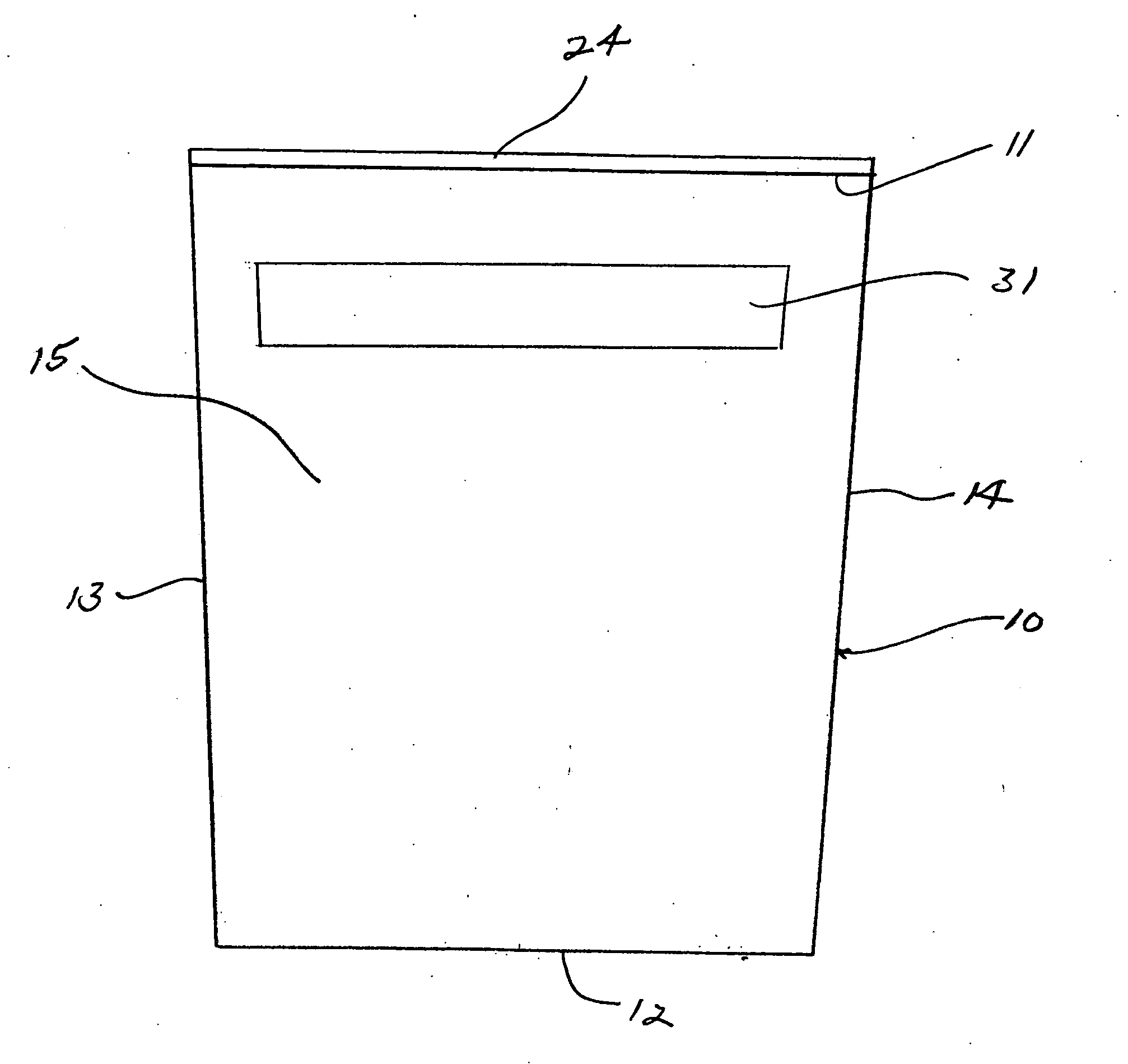
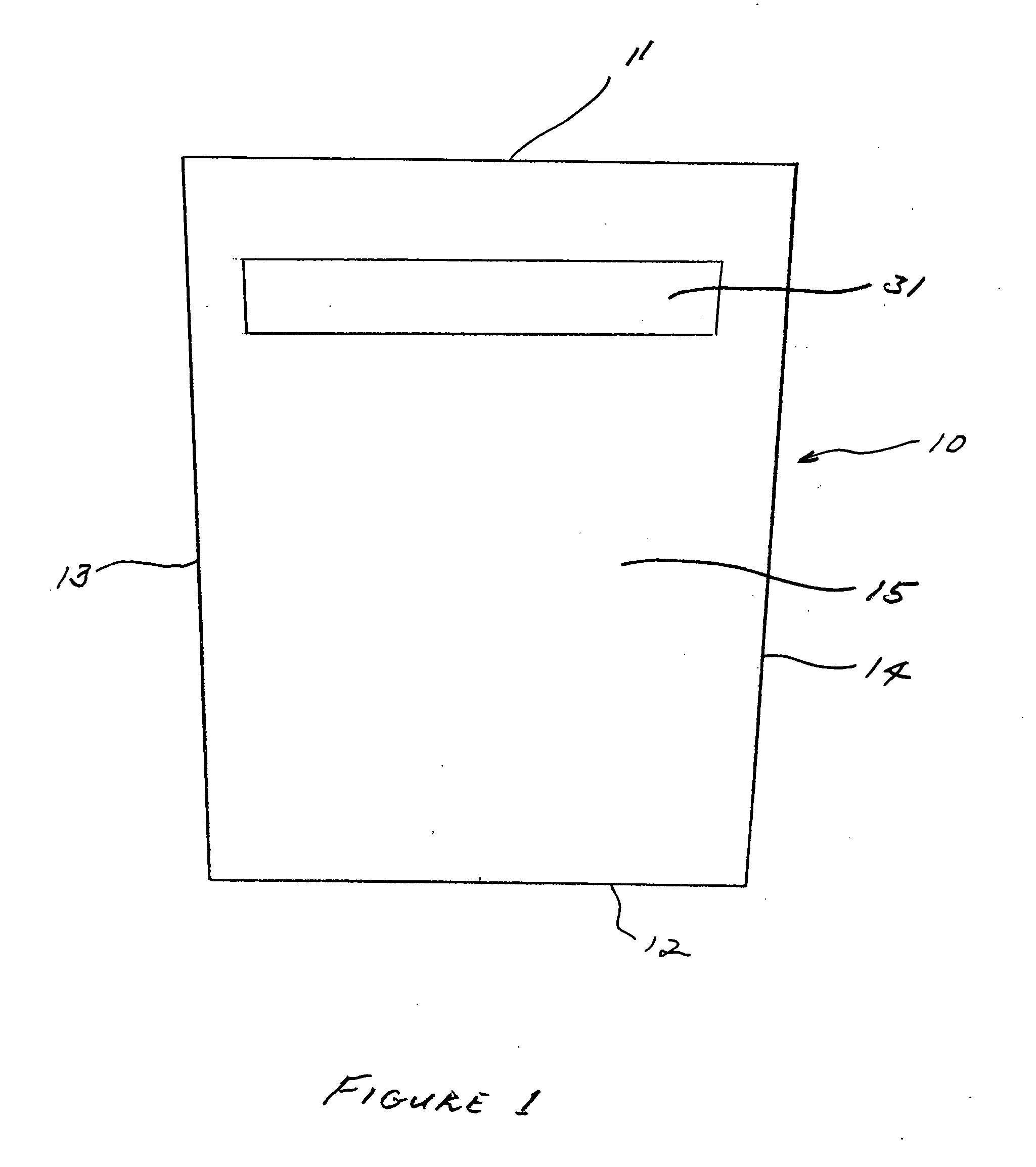
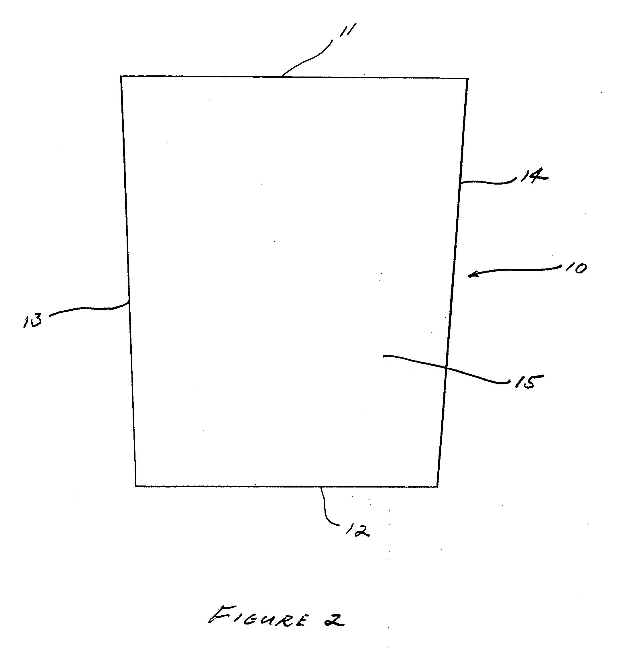
[0025] Referring now to the drawing figures, the primary structural component of the preferred embodiment of the invention, illustrated in FIGS. 1 through 10, comprises a planar panel 10 formed in a trapezoidal configuration, with top edge 11 and bottom edge 12 parallel to each other and with side edges 13 and 14 angled relative to each other. The width of panel 10 at its top edge 11 is greater than the width of the panel at its bottom edge 12. The first, or outer, face 15 of the panel is mirrored to reflect a mirror image from that face of the panel. The second, or inner, face 16 of the panel is formed of a non-reflective material, such as a plastic sheet. In the preferred embodiment the interior or core 17 of panel 10 is formed of a relatively rigid, lightweight foam material. The sheet forming inner face 16 is connected to the interior core 17 by convenient conventional means, such as screws or adhesive. The mirrored face of the panel is preferably formed of a material that is hi...


PUM


Abstract

A structural camouflage system includes as the primary structural component a planar panel with a reflective outer face, formed in a trapezoidal configuration with upper and lower edges of the panel in parallel relation, the panels connected in edge to edge orientation to form an enclosed structure with the reflective faces of the panels facing outward of the structure and inclined toward the surface upon which the structure rests, so that the panels reflect an image of the immediate foreground to more distant observer looking toward the structure, camouflaging the structure. In an alternative embodiment, a plurality of reflective strips are connected to vertical supports with each strip disposed at an angle so as to reflect a composite image of the immediate foreground to a more distant observer.

Description

RELATED APPLICATION DATA [0001] This application claims the benefit of U.S. Provisional Patent Application Ser. No. 60 / 601,927, filed Aug. 16, 2004, by the same applicant, titled “Structural Camouflage System”.FIELD OF THE INVENTION [0002] The present invention generally relates to camouflage and means of camouflaging objects, and in its preferred embodiments more specifically relates to a structural system for camouflaging or disguising the existence of any relatively rigid structure, both fixed and mobile. BACKGROUND OF THE INVENTION [0003] It is often desirable for a variety of reasons to disguise the existence of an object from observers. Various systems of camouflage have been developed for this purpose. Approaches to camouflage, as originally developed in the natural world and then adopted and copied by humans, include coloration and patterning, and mimicry of another object or structure. In the coloration and patterning approach, the surface of the object to be camouflaged is...

Claims


Application Information

Patent Timeline
Patent Type & Authority Applications(United States)
IPC IPC(8): E04H15/54
CPCA01M31/025
Inventor LEWIS, ROGER D.
Owner LEWIS ROGER D
Why Eureka
Try Eureka