Papers feeding device

Active Publication Date: 2007-01-11
FUJITSU LTD +1
View PDF17 Cites 7 Cited by
  • Summary
  • Abstract
  • Description
  • Claims
  • Application Information

AI Technical Summary

Benefits of technology

[0020] In addition to this, by a simple configuration such that the shaft of each pickup roller is connected to another shaft, such as the shaft of the existing feed roller, via a bracket in such a way as to be freely rotatable, each of the pickup rollers can be vertically moved independently, thereby reducing the number of parts of the devic

Problems solved by technology

However, sometimes height differences, such as undulations, slopes and the like due to deformation, such as creases, folding traces or the like, are generated on the uppermost surface of piled papers.
Furthermore, the complex configuration incurs the degradation of the reliability of the device, and is not suited for a bill depositing/drawing device, such as an ATM or the like, whose operational failure must be avoided with the highest priority.
H07-41186,

Method used


Image

  • Papers feeding device
  • Papers feeding device
  • Papers feeding device

Examples


Example

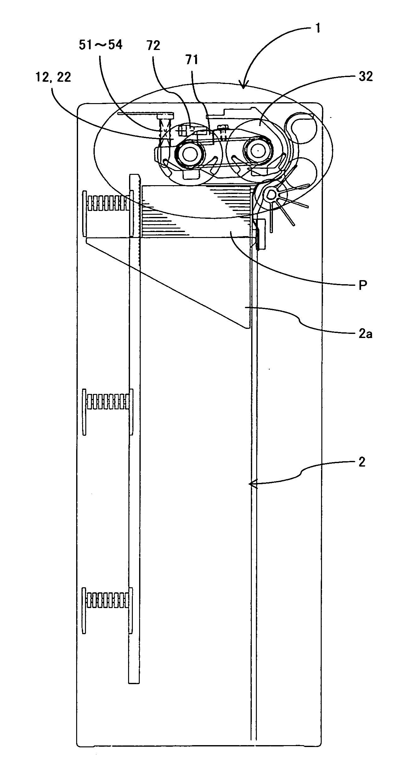
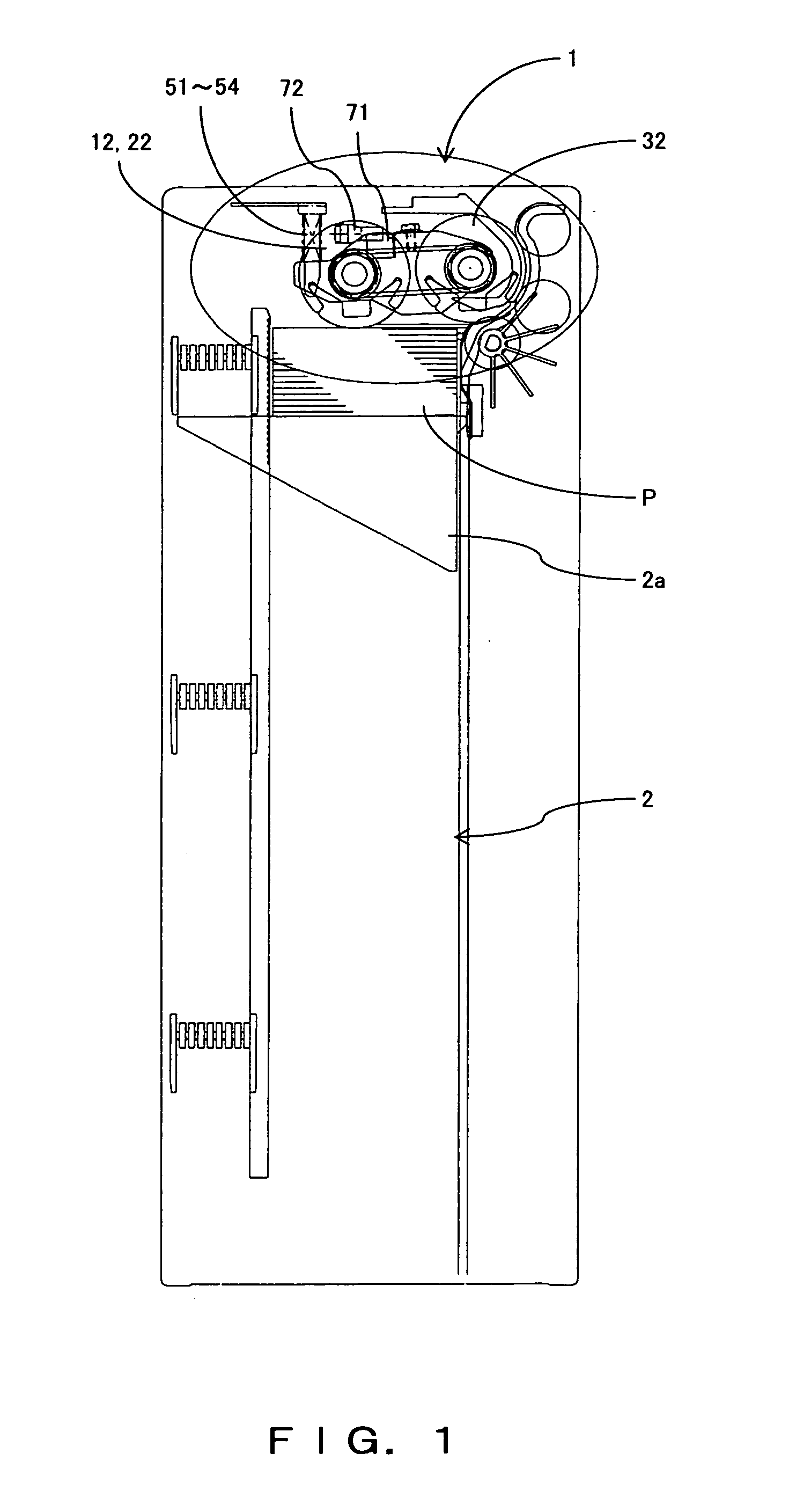
[0030] The papers feeding device in one preferred embodiment of the present invention is described below with reference to the drawings. In this preferred embodiment, as one example, the papers feeding device is provided as a part of a bill depositing / drawing device, such as an ATM or the like, and bills being papers are fed.

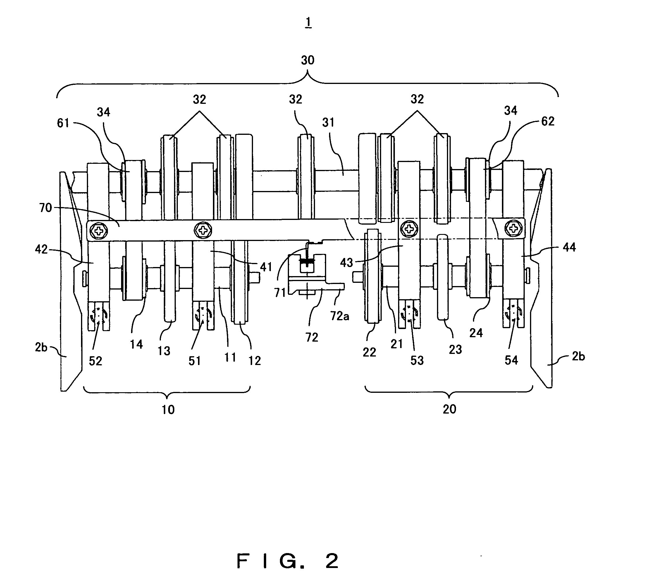
[0031]FIG. 1 shows the outline of the papers feeding device in one preferred embodiment of the present invention constituting a part of a bill depositing / drawing device. FIGS. 2 and 3 are the top view and partial section front view of the papers feeding device. FIG. 4 shows an optical sensor provided for the elastic support member of the papers feeding device. FIGS. 4A, 4B and 4C are its top view, front view and side view, respectively. FIG. 5 is the partial section front view of the papers feeding device, showing the state where bills (papers) of a variety of sizes are regulated by a guide unit.

[0032] In FIGS. 1-3, reference numeral 1 is the papers feeding de...


PUM


Abstract

A papers feeding device, comprising first and second feeding units 10 and 20 in which pickup rollers 12 and 22 are mounted on two or more independent shafts 11 and 21 disposed on the right and left sides of the device to be orthogonal to the carrying direction of papers P. The pickup rollers 10 and 20 are vertically moved independently while following up the height position of the uppermost surface of the piled papers P. The first and second feeding units 10 and 20 are connected by a plate elastic support member 70. The device also comprises a single optical sensor 72 for detecting the height position at the center of the elastic support member 70. The contact state of the pickup rollers 12 and 22 with the papers P is detected based on signals detected by the optical sensor 72.

Description

CROSS REFERENCE TO RELATED APPLICATION [0001] This application is a continuation of PCT application PCT / JP2005 / 004334 which was filed on Nov. 3, 2005.BACKGROUND OF THE INVENTION [0002] 1. Field of the Invention [0003] The present invention relates to a papers feeding device for feeding papers, such as bills piled in an accommodation unit or the like, onto a paper path one piece by one piece, and more particularly relates to a papers feeding device with a simple configuration, capable of normally feeding papers even when there are height differences, such as undulations, slopes and the like on the uppermost surface of piled papers. [0004] 2. Description of the Related Art [0005] For a printer, a copy machine, a bill depositing / drawing device, such as an automated teller machine (ATM) or the like, conventionally a papers feeding device for feeding papers, such as bills piled in an accommodation unit or the like, onto a paper path one piece by one piece is widely used. A general papers...

Claims


Application Information

Patent Timeline
IPC IPC(8): B65H3/32G07D1/00B65H1/04B65H3/06B65H7/14B65H7/18
CPCB65H1/14B65H3/0684B65H2701/1912B65H2553/41B65H2511/20B65H2511/152B65H7/18B65H7/14B65H2220/01B65H2220/02B65H2220/11
Inventor MIYAZAKI, HIROSHITAMAHASHI, TOMOYUKI
Owner FUJITSU LTD
Why Eureka
Try Eureka